Spindle Bearings
- Suitable for very high speeds
- Highest precision
- Assembly by pairs

Spindle bearings are a special type of single row angular contact ball bearings. They can absorb radial forces as well as axial and combined forces and are suitable for highest requirements of guiding and running accuracy, rigidity, increase in speed and decrease in friction due to their very limited tolerances. Spindle bearings cannot be disassembled and are not suitable for compensation of angular misalignments. They are mainly used for bearing the main spindle in the machine tools.
Dimensions and Tolerances
KRW supplies spindle bearings with P4S, which means the limited dimension tolerances P4 as well as the design and running tolerances P2, in accordance to DIN 620-2 (Tolerances for roller bearings) and ISO 492 (Radial bearings - Dimensional and geometrical tolerances). All other deviating or special tolerances must be specified with the order.
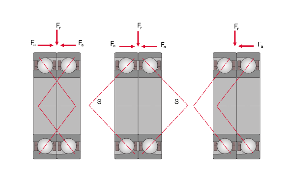
Different positioning of spindle bearings in X-, O-, and tandem arrangement
Bearing Design
Spindle bearings are self-latching bearings that cannot be disassembled. In addition to radial forces, they can absorb single-sided axial forces as well as, in combination with a second mirror-image arranged angular spindle bearing, two-sided axial forces and radial forces.
For combined bearing sets there is a distinction between O-, X-, or tandem arrangement based on pressure line contact. Bearings in X-arrangement are less suitable for the absorption of moments while the O-arrangement is very rigid and only allows small overturning clearance. For tandem arrangements, the contact lines of two bearings run in one direction which results in only single-sided absorption of axial forces. In the process, the axial load is absorbed by both bearings in the pair and the axial load capacity is increased.
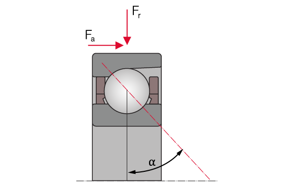
Spindle bearing in universal design; α – contact angle
The axial load capacity of a spindle bearing increases with a larger contact angle. The size of the contact angle is specified with the suffixes C (15°), D (20°) and E (25°).
KRW manufactures single spindle bearings in universal design which can be arranged next to each other in any order as well as fitted bearing sets with predefined bearing preload.
Preload
Spindle bearings are divided in different preload classes. These are not standardised. KRW preload classes are defined by suffixes. The preload must be chosen so the unloaded counter bearing still has enough preload in case of maximal axial force. Attention must be paid to the lifting forces. For this, consult the engineers of KRW Application Engineering.
Cage
By default, KRW spindle bearings are equipped with an outer ring riding laminated plastic window-type cage (suffix: TPA). Other cage designs are available on request or chosen for specific applications and labelled accordingly as suffix on the bearing.
Special Suffixes
| C | Modified internal design, contact angle 15° |
| D | Modified internal design, contact angle 20° |
| E | Modified internal design, contact angle 25° |
| TPA | Solid textile laminated phenolic window cage, rib-guided on outer ring |
| U | universal bearing, suffix followed by a letter indicating the preload level of the bearing. A distinction is made between: L - low preload M - medium preload H - high preload |
| DU | bearing set consisting of two universal bearings, suffix followed by a letter indicating the preload level of the bearing. A distinction is made between: L - low preload M - medium preload H - high preload |
| TU | bearing set consisting of three universal bearings, suffix followed by a letter indicating the preload level of the bearing. A distinction is made between: L - low preload M - medium preload H - high preload |
| QU | bearing set consisting of four universal bearings, suffix followed by a letter indicating the preload level of the bearing. A distinction is made between: L - low preload M - medium preload H - high preload |
| PU | bearing set consisting of five universal bearings, suffix followed by a letter indicating the preload level of the bearing. A distinction is made between: L - low preload M - medium preload H - high preload |
Compensation of Angular Misalignments
Spindle bearings are not suitable for compensation of misalignments. Misalignments cause harmful ball movement and produce additional stresses in the bearing which reduce its operating life.
Speed
The total energy balance of the bearing system is crucial for the reachable speed. It depends on:
- the number of bearings
- the arrangement of bearings
- the external load
- the preload class
- the lubrication and
- the heat dissipation.
The kinematic limiting speed nG is a practical mechanical limit value and is based on the mechanical fatigue strength of the rolling bearing as a function of its installation situation and lubrication. The limit speed of spindle bearings is, in contrast to other bearing types, determined by the chosen lubrication (nG Fett oder nG Öl) and must not be exceeded even under optimum operating conditions without prior consultation with KRW.
The limit speed for grease lubrication requires the use of high-speed grease with the correct quantity of grease in accordance with the operating conditions.
Limit speeds for bearing arrangements
If the spindle bearings are arranged in a rigid pre-stressed O-, X or tandem arrangement, the limit speeds of the single bearings shown in the bearing charts is reduced. For this purpose, a reduction factor fr is introduced which is defined according to bearing arrangement in the following table.
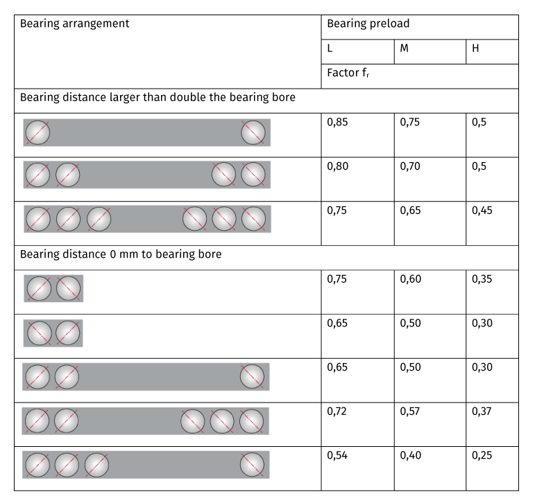
L: low preload, M: medium preload, H: high preload
Admissible Operating Temperatures
The admissible operating temperature of a bearing is limited by cage material, dimensional stability of the bearing components (ball race and rolling elements), as well as lubrication. By default, KRW bearings are stabilised up to 200°C (S1). KRW provides roller bearings for higher operating temperatures on request.
Dimensioning
Designing spindle bearings according to the service life in ISO 281 is possible but unusual. Spindle bearings are usually fatigue endurable, which means that they run below the fatigue limit load, which is why the principles of material fatigue do not apply. The design is decided through the bearing needs regarding load capacity, rigidity, and precision.
Spindle bearings are calculated statically in consideration of their load capacity according to the following formula:

| S0* | load ratio for fatigue endurability, dynamic load safety factor | [-] |
| C0 | basic static load rating (from bearing chart) | [kN] |
| P0* | equivalent bearing load is calculated with forces of the dynamic loads unsing the formula of the equivalent static load | [kN] |
Equivalent static bearing load P0*:
For spindle bearings, the following correlations apply:

| P0 | equivalent static load | [kN] |
| F0,r | static radial force | [kN] |
| F0,a | static axial force | [kN] |
| e | calculation factor, see chart | [-] |
| X | calculation factor, see chart | [-] |
| Y | calculation factor, see chart | [-] |
| Type | e | X | Y |
| Type C | 1,09 | 0,5 | 0,46 |
| Type D | 1,2 | 0,5 | 0,42 |
| Type E | 1,30 | 0,5 | 0,38 |
When there are multiple bearings in X-, O- or tandem arrangement being used in one bearing system, the external loads are distributed. The bearing with the biggest load must always be considered. The following table shows how the external loads are distributed between the combined bearings.
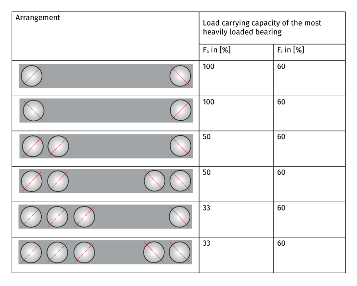
A more precise calculation for the spindle bearing design is the determination of the Hertzian contact stress between ball and raceways with the help of a calculation program and the ISO/TS 16281. The value must not exceed the maximum value of 2,000 N/mm².
Minimum Radial Load
A minimum load is required for the reliable operation of a rolling bearing. If the minimum load is not reached, slippage may occur. The minimum radial load for spindle bearings is roughly assumed to be 1% of the static load rating C0 of the bearing. If the value falls below this value, consult KRW Application Engineering.
