
Cylindrical Roller Bearings
full complement, double row
- Higher load ratings than bearings with cage
- High radial rigidity
- Only suited for low speeds

Double row full complement cylindrical roller bearings can absorb highest radial forces thanks to the highest possible number of rolling elements. The bearings are very rigid and especially suitable for space-efficient constructions. Speeds of full complement bearings are distinctly lower than those of cylindrical roller bearings with cage. Double row full complement cylindrical roller bearings can be disassembled and are easily installed or uninstalled. They are suitable for low speeds and only allow angular errors to a limited extent.
Dimensions and Tolerances
KRW supplies double row full complement cylindrical roller bearings with normal tolerance (PN) in accordance to DIN 620-2 (Tolerances for roller bearings) and ISO 492 (Radial bearings - Dimensional and geometrical tolerances). All other deviating or special tolerances must be specified with the order.

Full complement cylindrical roller bearings - Type NNC
Bearing Design
Double row full complement cylindrical roller bearings are dismountable and non-latching bearings that are distinguished in the types NNC, NNCL, NNCF, and ACB.
The inner ring of NNC bearings has three integral flanges while the outer ring has one integral flange and a loose shoulder ring. They can absorb axial forces from both directions and can therefore be used as fixed bearings. The support of the loose shoulder ring through structural design is the requirement for the absorption of axial forces from both directions.
Double row full complement cylindrical roller bearings are suitable for the absorption of highest radial forces and offer especially high radial rigidity.
Attention: Full complement cylindrical roller bearings are not compulsively designed as latching. The rolling elements can consequently fall out during disassembly.
Type NNCL (left), Type NNCF (right)
NNCL bearings are equipped with three solid flanges on the inner ring and a flange-less outer ring with two locking rings. The missing flange facilitates shaft clearance in axial direction of the housing and lets the bearing function as floating bearing. The inner ring of NNCF bearings has three integral flanges as well as one flange on the outer ring which facilitates the absorption of axial forces from a single direction.

By default, cylindrical roller bearings by KRW are designed with optimised contact areas between rolling elements and raceways. Due to the logarithmic profiling of the cylindrical rollers, damaging edge tension is avoided even with very high loads.
Cylindrical roller bearings can be delivered with cylindrical or tapered bore.
Bearing Clearance
KRW supplies double row cylindrical roller bearings in normal clearance (CN) in accordance with DIN 620-4 (Rolling bearing tolerances) and ISO 5753-1 (Rolling bearings - Internal clearance), but they are also available in all clearance classes with restricted clearance or special clearance. Bearing components with a standardised bearing type with identical standard clearance are interchangeable with each other. For clearance classes smaller than CN or restricted clearance classes, an interchange of bearing components is no longer possible because the components must be compatible.
| ||||||||
Special Suffixes
| V | full complement bearing (without cage) |
| VH | full complement bearing (without cage), self-retaining |
Compensation of Angular Misalignments
Double row full complement cylindrical roller bearings are not suitable for compensation of misalignments. Misalignments cause edge stresses between rolling elements and raceways and produce additional stresses in the bearing which reduce its operating life.
Speed
KRW distinguishes between kinematic limiting speed nG and thermal reference speed nth. The kinematic limiting speed is a practical mechanical limit value and is based on the mechanical fatigue strength of the rolling bearing as a function of its installation situation and lubrication. The limit speed must not be exceeded even under optimum operating conditions without prior consultation with KRW.
The thermal reference speed represents the equilibrium between the heat generated in the bearing by friction and the heat flow dissipated. It is standardised in DIN ISO 15312 (Rolling bearings - Thermal reference speed).
Admissible Operating Temperatures
The admissible operating temperature of a bearing is limited by cage material, dimensional stability of the bearing components (ball race and rolling elements), as well as lubrication. By default, KRW bearings are stabilised up to 200°C (S1). KRW provides roller bearings for higher operating temperatures on request.
Dimensioning
For dynamically loaded bearings
The service life formula according to ISO 281 L10 = (C/P)p for dynamically loaded bearings requires an equivalent load (P) from constant direction and size. To calculate P, calculation factors and the ratio of axial and radial load are required.
Equivalent Dynamic Bearing Load P
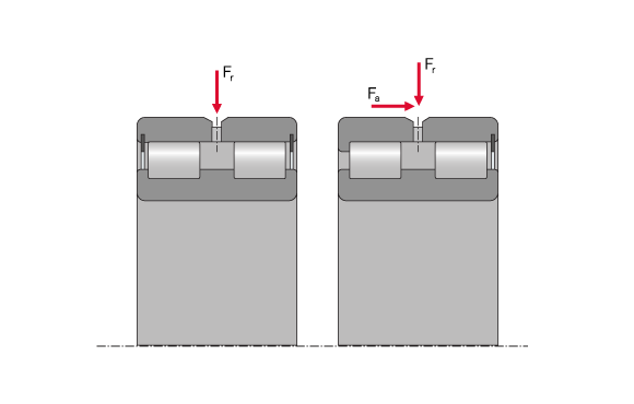
a) Floating bearing
For a purely radially loaded cylindrical roller bearing acting as a floating bearing, the following applies:

| P | equivalent dynamic load | [kN] |
| Fr | dynamic radial force | [kN] |
b) Fixed bearings
The equivalent bearing service life for axially loaded radial cylindrical roller bearings (cylindrical roller bearings with flanges on the inner and outer ring for axial shaft guidance) depends on the ratio Fa/Fr (axial force / radial force). The equivalent dynamic bearing load can then be determined using the following formula:

| P | equivalent dynamic load | [kN] |
| Fr | dynamic radial force | [kN] |
| Fa | dynamic axial force | [kN] |
| e | calculation factor, see chart | [-] |
| dimension series | factor e |
| 50 | 0,2 |
| 48, 49 | 0,4 |
If Fa/Fr > e, please consult KRW Application Technology.
For statically loaded bearings
Dynamic dimensioning loses its validity for bearings rotating at very low speeds (n x dm ≤ 4000 mm/min). The static load safety factor S0 is calculated as follows:

| S0 | static load safety factor | [-] |
| C0 | static load rating (from bearing chart) | [kN] |
| P0 | equivalent static bearing load | [kN] |
| n | Speed | [min-1] |
| dm | mean bearing diameter [dm = (D+d)/2] | [mm] |
Static load capacity

Admissible dynamic axial load capacity
The axial load capacity of a cylindrical roller bearing with flanges on the inner and outer ring depends primarily on the heat balance of the bearing and thus on the lubrication and friction conditions. For axial bearing loads there always must be a load-carrying lubricant film on the contact area between the front side of the rolling element and the flange. Before using the formula below, the following operating conditions must be met:
- viscosity ratio K ≥ 2
- max. misalignment between inner and outer ring ≤ 1 angular minute
- For grease lubrication, attention must be paid that there is an axial load that is changing in load direction so there always is enough lubrication at the contact point.
- EP additives are recommended

| FaH | admissible hydrodynamic stress limit | [N] |
| fb | for full complement bearings 0,0061 | [-] |
| dm | mean bearing diameter | [mm] |
| n | Speed | [min-1] |
| ν | operating viscosity | [mm²/s] |
For cylindrical roller bearings subject to high axial loads, the loaded flanges must be supported over the entire flange height. The height of the flanges can be taken from the bearing charts.
Minimum Radial Load
A minimum load is required for the reliable operation of a rolling bearing. If the minimum load is not reached, slippage may occur. The minimum radial load for full complement cylindrical roller bearings is roughly assumed to be 1.67% of the static load rating C0 of the bearing. If the value falls below this value, please consult KRW Application Technology.


