
General Basics
Functions of Rolling Bearings
Rolling bearings are machine elements and serve to support shafts and axles. Depending on their design, they absorb radial and/or axial loads and simultaneously enable rotation of the shaft or the components mounted on an axle. The force is transmitted via spherical or roller-shaped rolling elements. The advantages include the following points:
-
low friction even when starting from standstill
-
low cooling and lubrication requirements, grease lubrication usually sufficient
-
radial, axial and combined loading capacity achievable with little effort
-
almost backlash-free or preloaded operation possible
-
rolling bearings are available worldwide as ready-to-install standard part series
Bearing Types
Rolling bearings are divided into different bearing types and designs. Based on the ball bearing which represents the starting point, the starting point for the technical development of rolling bearings, today there are a large number of bearing types used for very specific operating conditions. Any design of a rolling bearing, however, will be a technical compromise determined by a wide variety of criteria. Rolling bearings are selected according to:
-
the available installation conditions,
-
the type and extent of the load,
-
speeds or motion cycles in general,
-
the required guidance accuracy of the machine and plant components,
-
the rigidity of the bearings,
-
the ambient conditions,
-
the installation and removal options
Apart from the technical parameters of a rolling bearing, such as static and dynamic load carrying capacity and permissible speeds, the bearing clearance or preload, the appropriate cage modification and the required lubrication method must be considered when selecting the bearing type.
Deep Groove Ball Bearing

Due to its simple construction and potential to absorb radial, axial, and combined loads, the deep groove ball bearing is described as the best known and most frequently used rolling bearing in literature. Deep groove ball bearings cannot be dismantled and only allow a small tilting angle. A further advantage is low friction and the associated high speed suitability.
Angular Contact Ball Bearings

Angular contact ball bearings are divided into single-row and double row bearings. They are suitable for very high speeds and absorb both axial and radial loads. Due to the contact angle, an axial load is generated even with a pure radial load. Single-row angular contact ball bearings should therefore always be fitted in pairs or in combination with another angular contact bearing. The contact angle differs depending on the dimensional series. In preloaded condition, angular contact ball bearings exhibit high rigidity and good guidance accuracy.
Four Point Contact Ball Bearings

Four-point contact bearings are a special type of single row angular contact ball bearings. They absorb alternating axial forces in both directions. A radial load on the bearings must be avoided. Four-point contact ball bearings are categorized into two types. Bearings with a split inner ring are referred to as QJ, bearings with a split outer ring as Q. The split design of the bearing rings ensures particularly easy assembly, e.g. in gear construction.
Cylindrical Roller Bearings

This bearing type has a very wide range of possible variations due to the wide variety of designs, without having to accept limitations of the high radial load capacity. As a rule, cylindrical roller bearings have a higher load capacity than comparable deep groove ball bearings. Individual designs of cylindrical roller bearings are capable of absorbing one-sided axial loads. Cylindrical roller bearings are manufactured as single-row, multiple-row, with and without cage, and can be dismantled. Therefore, they are easy to assemble for the user. Depending on the series, a maximum tilt angle of 3 to 4 angular minutes is permissible. Double row cylindrical roller bearings have a large radial load carrying capacity. Depending on the version, the absorption of low axial forces is possible. Tilting of multi-row bearings must always be avoided. Multi-row cylindrical roller bearings have the highest radial load carrying capacity and are mainly used in heavy industry (e.g. in rolling mills or roll crushers). Speed suitability is greatly reduced compared to single-row bearings. Full complement cylindrical roller bearings do not have a cage. Further cylindrical rollers are inserted in its place. These bearings have a significantly higher radial load carrying capacity than cage bearings, but the speed is lower due to rolling element friction.

Types of Cylindrical Roller Bearings
Tapered Roller Bearings

Tapered roller bearings absorb axial and radial forces similar to angular contact ball bearings. Due to its design, tapered roller bearings are capable of absorbing very high axial and radial forces. With a radial load, an axial force always occurs due to the contact angle which must be absorbed. For this reason, tapered roller bearings should always be fitted in pairs. The speed suitability of tapered roller bearings is lower than that of angular contact ball bearings. Tapered roller bearings can be dismantled and are divided into an outer ring and an inner ring with a Cone. Bearings are usually in metric but also in inch dimensions, the latter have a different designation scheme though.
Spherical Roller Bearings

Bearings with barrel rollers are divided into barrel roller bearings (single-row) and spherical roller bearings (double row). Both variants are able to compensate for misalignments. This is possible due to the spherical contour of the outer and inner ring raceways and the barrel-shaped rolling elements. Barrel roller bearings are used for lower loads. Spherical roller bearings are mainly used for high radial forces, shocks and misalignments. Compared to barrel roller bearings, spherical roller bearings are capable of absorbing larger axial forces. Both types cannot be dismantled.
Cylindrical Roller Thrust Bearings

Cylindrical roller thrust bearings are characterized by shaft and housing washers. These bearings are used for large axial forces. Some designs can be mounted on both sides. The absorption of radial loads is not possible due to the geometry. Due to the kinematics of axial cylindrical roller bearings, which are subject to an increasing relative speed of the rolling elements with increasing raceway diameter, their speed suitability is limited. A minimum axial load is required for optimum performance.
Deep Groove Thrust Ball Bearings

Deep groove thrust ball bearings are separable axial bearings manufactured in single and double direction. They are suitable for absorbing axial loads, but not radial loads. Due to the kinematic characteristics, medium to high speeds can be achieved with this bearing design. A minimum axial load is required for optimum function.
Special Bearings

KRW develops, designs and manufactures special designs on the basis of the bearing types mentioned above. Special designs are required above all when special properties of the rolling bearing have to be derived from the operating conditions. KRW offers current-insulated bearings (e.g. for electric motors), bearings with particularly thin-walled cross-sections (e.g. for textile machine construction) or bearings with a sophisticated internal design for realizing maximum load carrying capacities (e.g. for rolling mill construction).
Series Overview
| Rolling bearing design | Examples of series (further dimensional series on request) |
Deep Groove Ball Bearings, single-row | 160, 618, 619 |
Angular Contact Ball Bearings, single-row | 708, 709, 718, 719, 70, 72B, 73B |
Angular Contact Ball Bearings, double-row | SKZ, (0)32, (0)33 |
Four Point Contact Ball Bearings | Q10, QJ10, Q2, QJ2, Q3, QJ3, QJ4 |
Self-aligning Ball Bearings | 12, 13, 22, 23 |
Angular Contact Thrust Ball Bearings | 2344, 2347 |
Deep Groove Thrust Ball Bearings | 511, 512, 513, 514, 532, 533, 534, |
Cylindrical Roller Bearings, single-row | NU18, NU19, NU10, NU20, NU2, NU22 (corresponding to all designs, preferably in performance-enhanced version) NU3, NU23, NU4 |
Cylindrical Roller Bearings, double-row and multi-row | NN30, NNU49, NNU60 |
Cylindrical Roller Bearings (full complement), single-row | NCF...V, NJG23...V |
Cylindrical Roller Bearings (full complement), double-row | NNC...V, NNCL...V, NNCF...V |
Cylindrical Roller Bearings (full complement), multi-row | NNU60...V |
Cylindrical Roller Wheelset Bearings | WJ/WJP |
Cylindrical Roller Thrust Bearings | 811, 812, 893, 894, WS811, GS811, K811 |
Tapered Roller Bearings | 329, 320, 330, 331, 302, 322, 332, 303, 313, 323, 323 |
Barrel Roller Bearings / Spherical Roller Bearings (single-row) | 202, 203, 204 |
Spherical Roller Bearings (with cylindrical/tapered bore) | 222, 223, 230, 231, 232, 239, 240, 241, 248, 249 |
Spherical Roller Thrust Bearings | 292, 293, 294 |
Thin-section Bearings |
|
Current-insulated Bearings |
|
Special Bearings |
|
Clamping Sleeves | H2, H23, H3, H30, H31, H32, H39 |
Withdrawal Sleeves | AH2, AH3, AH22, AH23, AH 30, AH 31, |
L-section Rings | HJ |
Cylindrical Rollers | ZRO |
Barrel Rollers | TORO |
Tapered Rollers | KERO |
Technical Terms in Rolling Bearing Technology
Rolling Bearing Element Designations

| 1 | Width of bearing | 9 | Cicular groove |
| 2 | Outer ring | 10 | Outer ring front side |
| 3 | Outer ring on-board diameter | 11 | Outer ring raceway |
| 4 | Cage | 12 | Rolling element |
| 5 | Inner ring on-board diameter | 13 | Inner ring front side |
| 6 | Inner ring | 14 | Edge radius |
| 7 | Bore diameter of the inner ring | 15 | Inner ring raceway |
| 8 | Pitch circle diameter |
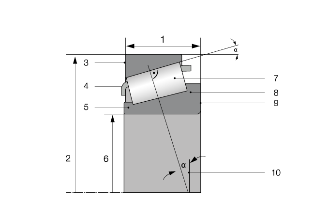
| 1 | Total widths of the bearing | 7 | Snap ring |
| 2 | Sheath diameter of the outer ring | 8 | Rolling element |
| 3 | Outer ring front side | 9 | Inner ring front side |
| 4 | Cage | 10 | Inner ring |
| 5 | Retaining lip | 11 | Contact angle |
| 6 | Bore diameter of the inner ring |

| 1 | Shaft washer | 4 | Rolling element |
| 2 | Cage | 5 | Mounting sleeve |
| 3 | Housing washer |
Standardisation and Nomenclature
Rolling bearings are internationally standardized in their dimensions (bore, outside diameter, width). The rolling bearing designations consist of logically structured combinations of letters and numbers reflecting the bearing’s design, size and properties. In addition to the standard bearings, there are special bearings or standard bearings in special designs whose designation system varies depending on the manufacturer. The DIN standard DIN 623 defines the basic principles for the designation and marking of rolling bearings.
Standardization of bearing types
| Design | Bearing type | Term | Standard number | ISO number |
Ball bearings | 1 | Self-aligning ball bearing | DIN 630 |
|
Ball bearings | 6 | Magneto bearing | DIN 615 |
|
Ball bearings | 6 | Deep groove ball bearing, single-row | DIN 615-1 | ISO 15 |
Ball bearings | 4 | Deep groove ball bearing, double-row | DIN 625-3 |
|
Ball bearings | 7 | Angular contact ball bearing, single-row | DIN 628-1 DIN 628-6 | ISO 15 |
Ball bearings | SKZ, (0) | Angular contact ball bearing, double-row | DIN 628-3 | ISO 15 |
Ball bearings | Q, QJ | Four point contact ball bearing | DIN 628-4 | ISO 15 |
Roller bearings | 2 | Spherical roller bearing, single-row (barrel roller bearing) | DIN 635-1 | ISO 15 |
Roller bearings | 2 | Spherical roller bearing, double-row | DIN 635-2 | ISO 15 |
Roller bearings | *) N, NU, NUP, NJ | Cylindrical roller bearing, single-row | DIN 5412-1 | ISO 15 |
Roller bearings | *) RNU, RN | Cylindrical roller bearing, ring with cage assemblies |
|
|
Roller bearings | *) NNU, NN | Cylindrical roller bearing, double-row | DIN 5412-4 | ISO 15 |
Roller bearings | *) NC | Cylindrical roller bearing (full complement), single-row |
| ISO 15 |
Roller bearings | *) NNC, NNCF | Cylindrical roller bearing (full complement), double-row | DIN 5412-9 | ISO 15 |
Roller bearings | *) WJ, WJP | Cylindrical roller wheelset bearing | DIN 5412-11 |
|
Tapered roller bearings | 3 | Tapered roller bearing, single-row | DIN 720 | ISO 355 |
Single direction deep groove thrust ball bearings with flat housing washer | 5 | Deep groove thrust ball bearings, single direction | DIN 711 | ISO 104 |
Single direction cylindrical roller thrust bearings | 8 | Cylindrical roller thrust bearing, single direction | DIN 722 | ISO 104 |
Single direction spherical roller thrust bearings | 2 | Spherical roller thrust bearing, single direction | DIN 728 | ISO 104 |
Double direction deep groove thrust ball bearings with flat housing washer | 5 | Deep groove thrust ball bearings, double direction | DIN 715 | ISO 104 |
Clamping sleeves | H | Rolling bearing clamping sleeve | DIN 5412 | ISO 113-1 |
Withdrawal sleeves | AH, AHX | Rolling bearing withdrawal sleeve | DIN 5416 | ISO 113-1 |
L-section rings for cylindrical roller bearings | HJ | for cylindrical roller bearings, single-row | DIN 5412-1 | ISO 15 |
| in standard design |
| ISO 246 | |
| in performance-enhanced design |
*) Further designs can be derived from the designs of cylindrical roller bearings listed in DIN 5401-1. Technical properties such as load ratings and speeds remain unchanged.
Rolling Bearing Designation System
In accordance with DIN 623-1, each rolling bearing is uniquely identified by a standard designation. The next figure shows an example of a bearing designation.

| Identification | ||||||
| I Prefixes | II Base character | III Suffixes | IV Supplementary character | |||
I.1 Bearing Parts | II.1 Bearing series | II.2 Bearing bore | NG 1: Internal construction NG 2: External shape NG 3: Cage NG 4.1: Tolerance classes NG 4.2: Bearing pairs NG 4.3 Bearing clearance NG 5.1: Material NG 5.2: Heat Treatment NG 6: Lubrication | NG 7.1: Technical specifications NG 7.2: Supplementary symbol according to manufacturer's specifications | ||
I.2 Material |
| Dimension series according to DIN 616 |
| |||
II.1.1 Bearing type | II.1.2 Width or height row | II.1.3 Diameter series | ||||
The order within the prefixes and base characters shall be as set out in Section I and Section II. The sequence of the suffixes and supplementary symbols may vary depending on the bearing design and modality. The order shown in Section III should be used for orders, but manufacturer specific variations are permitted.
Base characters must always be specified in full. The prefixes, suffixes and supplementary characters may then be missing from the abbreviation, if
-
according to Section I.2, only materials for the normal case are used,
-
the characteristics designated by them are not present,
-
no suffixes for special design variants (e.g. PN, CN and SN) are specified for the normal case in accordance with Section III,
-
no specifications have been agreed for these characteristics; the design shall then be determined at the choice of the manufacturer in accordance with the standard numbers.
Prefixes and suffixes can be added beyond the standard character strings. The statement of the standardized character string must be retained, it may only be supplemented.
f.e.: JP3 window cage made of sheet steel, manufacturer variant 3
The names of rolling bearing types introduced according to DIN ISO 5593 are used to form names in accordance with standards, indicating the type of rolling element and the raceway geometry, e.g. deep groove ball bearings, spherical roller bearings.
In order to keep the designation short, the "radial" prefix contained in customary designations is generally suppressed. Abbreviations are used for the same reason. The standardized designations and their abbreviations are listed in DIN 623-1. This table also contains the standard numbers. When the standard designation is formed, only the main standard number is specified.
Note: Related character blocks can be divided against each other by blanks or the graphic characters hyphen (-), slash (/), horizontal cross (x) or dot (●).
I Prefixes
I.1 Bearing Parts
The prefixes are used to identify parts of complete rolling bearings.
K | Cage with rolling elements (rolling element ring, e.g. K81110 for the axial cylindrical roller ring of the axial cylindrical roller bearing 81110) |
For some rolling bearing types (e.g. cylindrical roller bearings, tapered roller bearings) the free rings or the roller and cage assemblies with the non-detachable rings can also be ordered separately. These parts are identified by the prefixes before the base character.
L | Free ring (e.g. LNU 419 for the inner ring of the bearing NU 419 or LN 419 for the inner ring of the bearing N 419) |
R | Ring (inner or outer ring) with rolling element set (e.g. RNU 419 for the roller and cage assembly with the outer ring of the bearing NU 419 or RN 419 for the inner ring with the roller and cage assembly of the bearing N 419) |
WS | Shaft washer of a bearing |
GS | Housing washer of a bearing |
The parts marked L and R of a particular bearing type form a complete bearing arrangement. However, its full functionality can only be guaranteed if the parts are supplied by the same manufacturer. If the free ring consists of several parts, e.g. inner ring and flanged pulley on the cylindrical roller bearing NUP, the prefix L for the inner ring with associated flanged pulley applies accordingly.
I.2 Material
Inner and outer rings and rolling elements are normally made of rolling bearing steel according to DIN EN ISO 683-17.
Rolling bearings made of stainless steel usually have the prefix S (e.g. S 6205) or W (e.g. W 6205). A comparison of conventional rolling bearing material is shown in chapter "Rolling bearing material in comparison".
II Base Character
The base character indicates the type and size of the bearing. It usually consists of one character or character group for each (exceptions see below):
-
Bearing series (see section II.1)
-
Bearing bore (see section II.2)
The above system does not apply to needle roller/axial cylindrical roller bearings, needle roller/axial ball bearings, drawn cup needle roller bearings, drawn cup needle bushes, drawn cup needle roller bearings, radial needle roller and cage assemblies, axial needle roller and cage assemblies and axial washers. Here the base character is composed of characters for :
-
Bearing design
-
Characteristic dimension(s)
The corresponding assembly system is shown in DIN 623.
II.1 Bearing Series
The bearing series consists of the bearing type and the dimensional series. Each bearing series is identified by a group of numbers or letters or by a combination of numbers and letters.
There are two different designation systems for tapered roller bearings according to DIN 720 and ISO 355. DIN 720 corresponds to the rules of this standard, ISO 355 contains its own systematics.
II.2 Bearing bore
The symbol for the bearing bore consists of digits and is generally appended directly to the symbol for the bearing series, but in defined cases also with a slash.
Symbols for bearing bore:
| Bore diameter (mm) | Symbol for bearing bore | Examples | |
| over | to | ||
| - | 9 | The bore dimension in mm is appended unencrypted with a slash to the abbreviation for the bearing series, even for decimal fraction dimensions. | Deep groove ball bearing of bearing series 618 with 3 mm bore diameter of the inner ring: 618/3 |
In the following exceptions, the slash was removed: Deep groove ball bearings: 602, 603, 604, 605, 606, 607, 608, 609, 623, 624, 625, 626, 627, 628, 629, 633 634, 635, 636, 637, 638, 639 Self-aligning ball bearings: 108, 126, 127, 129, 135 Angular contact ball bearing: 705, 706, 707, 708, 709 (not included in product standards, previously common types) | Deep groove ball bearing of bearing series 62 with 5 mm bore diameter of the inner ring: 62 5 Self-aligning ball bearing of bearing series 12 with 6 mm bore diameter of the inner ring: 12 6 Angular contact ball bearings of bearing series 70 with 6 mm bore diameter of the inner ring: 70 6 | ||
| 10 | 17 | Bore code in bearing row 00 = 10 mm bore For all bearing series except E, B0, L, M, UK, UL, UM and radial insert ball bearings YEN 203/12, YEN 203/15, YAL 203/12, YAL 203/15 | Deep groove ball bearing of bearing series 62 with 12 mm bore of the inner ring: 6201 Needle roller bearings of bearing series NA 49 with 15 mm bore of inner ring: NA4902 |
| 20 | 480 | Bore code = 1/5 of the bore diameter in mm on bearing row For diameters up to 45 mm, a zero is set before the hole number For all bearing series except series E, B0, L, M, UK, UL, UM and bores 22, 28 and 32 mm as well as radial insert ball bearing YEL 214/65 | Spherical roller bearing of bearing series 232 with 120 mm bore of inner ring: 23224 Angular contact ball bearings of bearing series 73 with 30 mm bore of the inner ring: 7306 |
| Intermediate sizes | Bore diameter in mm for intermediate sizes with 22, 28 and 32 mm bearing bore; bore diameter separated by slash on bearing row | Deep groove ball bearings of bearing series 62 with 22 mm bore of inner ring: 62/22 | |
| 500 | all sizes | Bore diameter in mm separated by slash on bearing row, for new designs follow dimension plan DIN 616 | Spherical roller bearing of bearing series 230 with 500 mm bore of inner ring: 230/500 |
| all sizes | Bore diameter in mm to bearing series E, B0, L, M, UK, UL and UM | Magneto bearing of the bearing series B0 with 17 mm bore of the inner ring: B017 | |
III Suffixes
Suffixes are added after the base character. They are used to identify
-
NG 1: internal construction
-
NG 2: external shape
-
NG 3: cage design
-
NG 4.1: tolerances
-
NG 4.2: bearing pairs
-
NG 4.3: bearing clearance
-
NG 5.1: material
-
NG 5.2: heat treatment
-
NG 6: lubrication
NG 1 - Internal Construction
| A | Modified internal design |
| A | Spherical roller bearings: Modified internal design, inner ring with two lateral retaining ribs and one central rib |
| A | Tapered roller bearings: Modified internal design |
| A | Cylindrical roller bearing: Modified internal design |
| B | Modified internal design |
| B | Angular contact ball bearings: Modified internal design, contact angle 40° |
| B | Tapered roller bearings: Modified internal design, contact angle 20° |
| C | Modified internal design |
| C | Angular contact ball bearings: Modified internal design, contact angle 15° |
| C | Spindle bearings: Modified internal design, contact angle 15° |
| E | Modified internal design |
| E | Angular contact ball bearings: Modified internal design, contact angle 25° |
| E | Spindle bearings: Modified internal design, contact angle 25° |
| E | Cylindrical roller bearings: Modified internal design, Increased capacity design |
| EX | Cylindrical roller bearings: Modified internal design, adapted according to norm, Bearing parts not interchangeable with the previous E version |
| EA | Spherical roller bearings: Modified internal design, inner ring with two lateral retaining ribs |
| EA | Spherical roller thrust bearings: Modified internal design, in connection with mounting dimensions |
| D | Modified internal design |
| D | Angular contact ball bearings: Modified internal design, contact angle 20° |
| D | Spindle bearings: Modified internal design, contact angle 20° |
NG 2 - External Shape
| DH | Thrust bearings, single direction with two housing washers |
| DS | Thrust bearings, single direction with two shaft washers |
| EK | Thrust ball bearings without housing washer |
| H | Bearings with two lubrication holes on the non-thrust side in the outer ring |
| H | Spindle bearing: Bearings with two lubrication holes on the non-thrust side in the outer ring |
| H1 | Bearings with two lubrication holes on the thrust side in the outer ring |
| H1 | Spindle bearing: Bearings with two lubrication holes on the thrust side in the outer ring |
| K | Tapered bore, taper 1:12 |
| K30 | Tapered bore, taper 1:30 |
| L | Bearings with annular groove and two lubrication holes on the non-thrust side and two annular groove fitted with O-rings in the outer ring |
| L | Spindle bearing: Bearings with annular groove and two lubrication holes on the non-thrust side and two annular groove fitted with O-rings in the outer ring |
| L1 | Bearings with annular groove and two lubrication holes on the thrust side and two annular groove fitted with O-rings in the outer ring |
| N | Snap ring groove in the outer ring |
| NR | Snap ring groove in the outer ring, with snap ring |
| NB | Snap ring groove in the outer ring (with one-sided sealed bearings on the sealed side) |
| N1 | One locating slot in one outer ring side face |
| N2 | Two locating slot in one outer ring side face, 180° apart |
| N3 | One locating slot on one side face and one snap ring groovein on the other side in the outer ring |
| N4 | Two locating slot in one outer ring side face and one snap ring groovein on the other side in the outer ring |
| N5 | One locating slot and snap ring groove on one side in the outer ring |
| N6 | Two locating slot and one snap ring groove on one side in the outer ring |
| OB | Cylindrical roller bearing without loose rib (does not apply to NUP and NP execution) |
| T.. | Suffix T followed by a number indicates the total width of matched bearings, arranged back-to-back or in tandem |
| R | Bearings with a flange on outer ring |
| S | Bearings with annular groove and three lubrication holes in the outer ring |
| S6 | Bearings with annular groove and six lubrication holes in the outer ring |
| SIR | Bearings with annular groove and three lubrication holes in the inner ring |
| SIR6 | Bearings with annular groove and six lubrication holes in the inner ring |
| W | Bearings without annular groove and lubrication holes in the outer ring |
| W20 | Bearings with three lubrication holes in the outer ring |
| W22 | Bearings with two lubrication holes in the inner ring |
| W24 | Bearings with four lubrication holes in the inner ring |
| W26 | Bearings with six lubrication holes in the inner ring |
| W30 | Bearings with three lubrication holes in the inner ring |
| W77 | Bearing with plug added lubrication holes in the outer ring |
| X | Tapered roller bearings: Bearings with, boundary dimensions adapted to ISO standards |
NG 3 - Cage Design
| M | Solid brass cage, rolling elements guided |
| MA | Solid brass cage, rib-guided on outer ring |
| MAS | Solid brass cage, rib-guided on outer ring, with lubricating grooves |
| MB | Solid brass cage, rib-guided on inner ring |
| MBS | Solid brass cage, rib-guided on inner ring, with lubricating grooves |
| M2 | Two-piece solid brass cage, riveted (steel rivet), rolling elements guided |
| M2A | Two-piece solid brass cage, riveted (steel rivet), rib-guided on outer ring / guided on housing washer |
| M2B | Two-piece solid brass cage, riveted (steel rivet), rib-guided on inner ring / guided on shaft |
| M2AS | Two-piece solid brass cage, riveted (steel rivet), rib-guided on outer ring/ guided on housing washer, with lubricating grooves |
| M2BS | Two-piece solid brass cage, riveted (steel rivet), rib-guided on inner ring / guided on shaft, with lubricating grooves |
| M3 | Two-piece solid brass cage, crosspiece riveted, rolling elements guided |
| M3A | Two-piece solid brass cage, crosspiece riveted, rib-guided on outer ring / guided on housing washer |
| M3B | Two-piece solid brass cage, crosspiece riveted, rib-guided on inner ring / guided on shaft |
| M3AS | Two-piece solid brass cage, crosspiece riveted, rib-guided on outer ring / guided on housing washer |
| M3BS | Two-piece solid brass cage, crosspiece riveted, rib-guided on inner ring, with lubricating grooves |
| M4 | Two-piece solid brass cage, bolted, rolling elements guided |
| M4A | Two-piece solid brass cage, bolted, rib-guided on outer ring / guided on housing washer |
| M4B | Two-piece solid brass cage, bolted, rib-guided on inner ring |
| M4AS | Two-piece solid brass cage, bolted, rib-guided on outer ring / guided on housing washer, with lubricating grooves |
| M4BS | Two-piece solid brass cage, bolted, rib-guided on inner ring / guided on shaft, with lubricating grooves |
| MP | Solid brass window cage, rolling elements guided |
| MPA | Solid brass window cage, rib-guided on outer ring / guided on housing washer |
| MPAD | Solid brass window cage, rib-guided on outer ring, by special cage pocket geometry of the cage with the rolling elements can be removed from the outer ring |
| MPB | Solid brass window cage, rib-guided on inner ring / guided on shaft |
| MPAS | Solid brass window cage, rib-guided on outer ring / guided on housing washer, with lubricating grooves |
| MPBS | Solid brass window cage, rib-guided on inner ring / guided on shaft, with lubricating grooves |
| MPE | Solid brass window cage, modified, rolling elements guided |
| MPEA | Solid brass window cage, modified, rib-guided on outer ring / guided on housing washer |
| MPEB | Solid brass window cage, modified, rib-guided on inner ring / guided on shaft |
| MPEAS | Solid brass window cage, modified, rib-guided on outer ring / guided on housing washer, with lubricating grooves |
| MPEBS | Solid brass window cage, modified, rib-guided on inner ring / guided on shaft, with lubricating grooves |
| ALP | Solid aluminum alloy window cage, rolling elements guided |
| F | Solid steel cage, rolling elements guided |
| F2 | Two-piece solid steel cage, riveted (steel rivet), rolling elements guided |
| FP | Solid steel window cage, rolling elements guided |
| FR | Pin type cage, rolling elements guided |
| HPA | Solid bronze window cage, rib-guided on outer ring / guided on housing washer |
| J | Sheet steel cage, rolling elements guided |
| JH | Sheet steel snap-type cage, rolling elements guided |
| JN | Sheet steel cage, riveted (steel rivet), rolling elements guided |
| JP | Sheet steel window cage, rolling elements guided |
| T | Solid textile laminated phenolic cage, rolling elements guided |
| TA | Solid textile laminated phenolic cage, rib-guided on outer ring / guided on housing washer |
| TB | Solid textile laminated phenolic cage, rib-guided on inner ring / guided on shaft |
| TH | Solid snap-type textile laminated phenolic cage, rolling elements guided |
| THA | Solid snap-type textile laminated phenolic cage, rib-guided on outer ring / guided on housing washer |
| THB | Solid snap-type textile laminated phenolic cage, rib-guided on inner ring / guided on shaft |
| TP | Solid textile laminated phenolic window cage, rolling elements guided |
| TPA | Solid textile laminated phenolic window cage, rib-guided on outer ring / guided on housing washer |
| TPA | Spindle bearing: Solid textile laminated phenolic window cage, rib-guided on outer ring |
| TPB | Solid textile laminated phenolic window cage, rib-guided on inner ring / guided on shaft |
| TE | Solid PEEK (polyether ether ketone) cage, rolling elements guided |
| TEA | Solid PEEK (polyether ether ketone) cage, rib-guided on outer ring / guided on housing washer |
| TEPA | Solid PEEK (polyether ether ketone) window cage, rib-guided on outer ring / guided on housing washer |
| TN | Solid polyamide PA66 cage, rolling elements guided |
| TNH | Solid snap-type polyamide PA66 cage, rolling elements guided |
| TNP | Solid polyamide PA66 window cage, rolling elements guided |
| TV | Solid polyamide PA66-GF25 window cage, rolling elements guided |
| TVH | Solid snap-type polyamide PA66-GF25 cage, rolling elements guided |
| TVP | Solid polyamide PA66-GF25 window cage, rolling elements guided |
| Y | Sheet brass cage, rolling elements guided |
| V | Full complement ball or roller bearing (without cage) |
| VH | Full complement ball or roller bearing (without cage), self-retaining |
NG 4.1 - Tolerance
| PN | Dimensional and running tolerances according to ISO to class Normal, is not included in bearing designations |
| P6X | Dimensional and running tolerances according to ISO to class 6X |
| P6 | Dimensional and running tolerances according to ISO to class 6 |
| P5 | Dimensional and running tolerances according to ISO to class 5 |
| P4 | Dimensional and running tolerances according to ISO to class 4 |
| P4S | KRW standard, better than dimensional and running tolerances according to ISO to class 4 |
| P2 | Dimensional and running tolerances according to ISO to class 2 |
| SP | Tolerance class (KRW), Special precision |
| UP | Tolerance class (KRW), Ultra precision |
NG 4.2 - Bearing Pairs
| DB | Two bearings matched for mounting back-to-back, suffix DB followed by sign indicates the the internal preload or clearance of bearing set |
| DF | Two bearings matched for mounting face-to-face, suffix DF followed by sign indicates the the internal preload or clearance of bearing set |
| DT | Two bearings matched for mounting tandem, suffix DT followed by sign indicates the the internal preload or clearance of bearing set |
| DG | Two bearings matched for mounting universal set, suffix DG followed by sign indicates the the internal preload or clearance of bearing set |
| TG | Three bearings matched for mounting universal set, suffix TG followed by sign indicates the the internal preload or clearance of bearing set |
| QG | Quad bearings matched for mounting universal set, suffix QG followed by sign indicates the the internal preload or clearance of bearing set |
| PG | Five bearings matched for mounting universal set, suffix PG followed by sign indicates the the internal preload or clearance of bearing set |
| TBT | Three bearings matched for mounting tandem and back-to-back, suffix TBT followed by sign indicates the the internal preload or clearance of bearing set |
| TFT | Three bearings matched for mounting tandem and face-to-face, suffix TFT followed by sign indicates the the internal preload or clearance of bearing set |
| TT | Three bearings matched for mounting tandem, suffix TFT followed by sign indicates the the internal preload or clearance of bearing set |
| QBC | Quad bearings matched for mounting tandem and back-to-back //\\, suffix QBC followed by sign indicates the the internal preload or clearance of bearing set |
| QBT | Quad bearings matched for mounting tandem and back-to-back ///\, suffix QBT followed by sign indicates the the internal preload or clearance of bearing set |
| QFC | Quad bearings matched for mounting tandem and face-to-face \\//, suffix QFC followed by sign indicates the the internal preload or clearance of bearing set |
| QFT | Quad bearings matched for mounting tandem and face-to-face \///, suffix QFT followed by sign indicates the the internal preload or clearance of bearing set |
| PBC | Five bearings matched for mounting tandem and face-to-face ///\\, suffix PBC followed by sign indicates the the internal preload or clearance of bearing set |
| PBT | Five bearings matched for mounting tandem and face-to-face ////\, suffix PBC followed by sign indicates the the internal preload or clearance of bearing set |
| U | Spindle Bearing: Universal bearing, suffix U followed by a letter indicates the the internal preload of bearing set. It is distinguished: L - light preload M - medium preload H - heavy preload |
| DU | Spindle Bearing: Two bearings matched for mounting universal set, suffix DU followed by a letter indicates the the internal preload of bearing set. It is distinguished: L - light preload M - medium preload H - heavy preload |
| TU | Spindle Bearing: Three bearings matched for mounting universal set, suffix TU followed by a letter indicates the the internal preload of bearing set. It is distinguished: L - light preload M - medium preload H - heavy preload |
| QU | Spindle Bearing: Quad bearings matched for mounting universal set, suffix QU followed by a letter indicates the the internal preload of bearing set. It is distinguished: L - light preload M - medium preload H - heavy preload |
| PU | Spindle Bearing: Five bearings matched for mounting universal set, suffix PU followed by a letter indicates the the internal preload of bearing set. It is distinguished: L - light preload M - medium preload H - heavy preload |
NG 4.3 - Bearing Clearance
| C1 | Radial or axial internal clearance smaller than C2 |
| C2 | Radial or axial internal clearance smaller than CN |
| CN | Radial or axial internal clearance bigger than C2 and smaller than C3, is not included in bearing designations |
| C3 | Radial or axial internal clearance bigger than CN |
| C4 | Radial or axial internal clearance bigger than C3 |
| C5 | Radial or axial internal clearance bigger than C4 |
| ..L | Internal clearance, reduced clearance range corresponding to the lower half of the actual clearance range |
| ..M | Internal clearance, reduced to half the clearance range corresponding to the middle of the actual clearance range |
| ..H | Internal clearance, reduced clearance range corresponding to the upper half of the actual clearance range |
| ..NA | Internal clearance reduced, Bearing parts not interchangeable |
| ..VG | Bearings prepared for internal clearance, bearing with rough ground ring raceway, for CN (Normal), suffix CN can be omitted |
| VG.. | Suffix VG followed by a number indicates the middle raceway roughing dimension on the ring in the bearing |
| A.. | Axial internal clearance in µm |
| R.. | Radial internal clearance in µm |
| CA | Bearing for universal matching for fitting in pairs in an X or O arrangement intended, axial internal clearance smaller than Normal (CB) |
| CB | Bearing for universal matching for fitting in pairs in an X or O arrangement intended, axial internal clearance Normal |
| CC | Bearing for universal matching for fitting in pairs in an X or O arrangement intended, axial internal clearance greater than Normal (CB) |
| C | Bearing for universal matching for fitting in pairs in an X or O arrangement intended, axial internal clearance in µm |
| GA | Bearing for universal matching for fitting in pairs in an X or O arrangement intended, light preload |
| GB | Bearing for universal matching for fitting in pairs in an X or O arrangement intended, moderate preload |
| GC | Bearing for universal matching for fitting in pairs in an X or O arrangement intended, heavy preload |
| G.. | Bearing for universal matching for fitting in pairs in an X or O arrangement intended, axial internal preload in µm |
NG 5.1 - Material
| HA.. | Bearings or bearing parts are made of casehardening steel, suffix followed by a number indicates the affected parts group |
| HC.. | Hybrid bearing, bearing parts are made of silicon nitride Si3N4, suffix followed by a number indicates the affected parts group |
NG 5.2 - Heat Treatment
| HB.. | Bearings or bearing parts hardened bainitic, suffix followed by a number indicates the affected parts group |
| SN | Bearing rings or washer heat stabilized for operating temperatures up to 120 °C, is not included in bearing designations |
| S0 | Bearing rings or washer heat stabilized for operating temperatures up to 150 °C |
| S1 | KRW Standard; Bearing rings or washer heat stabilized for operating temperatures up to 200 °C |
| S2 | Bearing rings or washer heat stabilized for operating temperatures up to 250 °C |
| S3 | Bearing rings or washer heat stabilized for operating temperatures up to 300 °C |
| S4 | Bearing rings or washer heat stabilized for operating temperatures up to 350 °C |
| ..A | Outer rings or housing washer heat stabilized according to Suffix for dimensionally stability |
| ..B | Inner rings or shaft washer heat stabilized according to Suffix for dimensionally stability |
NG 6 - Lubrication
According to customer specification
Here you can find the KRW Suffix List (PDF).
IV Supplementary character
For specifications that go beyond the symbols from I to III, manufacturer-related supplementary symbols can be specified. The commitments of the relevant product standards must be kept. With addition signs, specifications beyond the product standard are made or tolerances are narrowed.
NG 7.1 - Technical Specification
| BR.. | Bearings or bearing parts coated (burnished), suffix followed by a number indicates the affected parts group |
| SJ.. | Insulated bearing or bearing parts, suffix followed by a number indicates the affected parts group. There is a distinction between: 5 - Insulated bearing up to 500 V, coated outer ring 10 - Insulated bearing up to 1.000 V, coated outer ring 30 - Insulated bearing up to 3.000 V, coated outer ring ..J - Coated inner ring |
NG 7.2 - Supplementary symbol according to manufacturer's specification
| FV1 | Traction motor bearings for railway applications according to DIN 43283:1982 |
| FV2 | Bearing for railway axleboxes in accordance with EN 12080, class 1 |
| FV3 | Bearing according to VGN 3050 |
Main Dimensions
Rolling bearings can be used universally as ready-to-install machine elements. This is mainly because the main dimensions of the common bearings are standardized. ISO 15 applies to radial bearings (except tapered roller bearings), ISO 355 to metric tapered roller bearings and ISO 104 to axial bearings. The dimension plans of the ISO standards were adopted in DIN 616 and DIN ISO 355 (metric tapered roller bearings).
In the dimension plans of DIN 616, several outside diameters and widths are assigned to one bearing bore. Common diameter series are 7, 8, 9, 0, 1, 2, 3, 4 (outer diameter increasing in this order). Within each diameter row there are several width rows 8, 0, 1, 2, 3, 4, 5 (with larger number increasing width).
The two-digit number for the dimension series contains first the number of the width series (for axial bearings of the height series), and second the number of the diameter series. When using the width and diameter series in practice, figures are omitted for some bearing types, e.g. for cylindrical roller bearings of width series "0" (NU0220 à NU220)

Dimensional series for radial bearings

Dimensional series for axial bearings
Designation Example
The following applies to the designation of a spherical roller bearing:

Way of Speaking
The base characters are to be separated between the bearing series and the bearing bore. The separation of the character block for the dimension series and the connection of the separated character with the character for the bearing type are not permitted when speaking.
Correct Speech:
618/3 | six hundred and eighteen slash three |
625 | sixty-two five |
6205 | sixty-two zero five |
30205 | three hundred two zero five |
22310 | two hundred and twenty-three ten |
NJ210 | N J two ten |
Cage Types and Designs
General Information
The bearing cage is an important component in the rolling bearing with the following functions:
-
keeps the rolling elements at a distance to prevent contact
-
ensures an equal distance between the rolling elements, thus ensuring even load distribution
-
guides the rolling elements
-
transmits circumferential forces
-
prevents the rolling elements from falling out in bearings that can be dismantled and pivoted
A distinction is made between sheet metal cages, one-piece, and multi-piece solid cages made of different materials.
Pressed Steel Cage
Pressed steel cages are bearing cages which are almost always punched or pressed from sheet steel. Rarely, brass sheet is also used. A lower weight and a good lubricant supply to the bearing interior are advantages over solid cages.

Solid Cages
Solid cages are usually used for high cage strength requirements and temperatures up to 250°C. Brass, steel, bronze, aluminum, sintered iron, plastics or hard fabric are the materials used. Solid cages made of metal or hard fabric are produced by turning and milling, solid cages made of plastic by injection molding into molds.
For large, highly loaded bearings and for small series, solid cages, primarily made of brass and steel, are an advantage. Relatively low inertial forces have solid cages made of light metal, plastic or hard tissue and are therefore used in high-speed applications in an outboard version.
Cages made of glass fiber reinforced polyamide (PA66 GF25) are installed in many large series bearings, which have a low weight, high elasticity and good sliding and emergency running properties. This has a positive effect on the life of the bearing.
Special operating conditions require a specially selected cage. However, the operating temperature limit is 120 ° C.

Pin Type Cages
Rolling elements with a central axial bore are used for rolling bearings with a welded pin cage, mostly cylindrical roller bearings, tapered roller bearings and more rarely spherical roller bearings. A steel bolt leads through this hole, which connects two side cage washers and thus ensures high strength.

Cage Guides
A distinguishing feature is that cages can be guided differently depending on the application. The cages are most frequently guided by the rolling elements (without suffixes). Cage guide on the bearing outer ring, or also known as outboard guidance, is indicated with the suffix A. Cage guide on bearing inner ring, also known as inboard guidance, is indicated by the suffix B.

Bearing Tolerances
Bearing Tolerances ensure the rolling bearing interchangeability. The values of the dimensional and running tolerances are given in DIN 620. Bearings are generally manufactured in tolerance classes PN, other tolerance classes are available on request or are selected depending on the application.
Symbols Bore Diameter
| d | Nominal diameter of the bore |
| d1 | Diameter of the theoretical taper surface at the wide end of a tapered bore |
| d2 | Nominal diameter of the bore of the shaft located washer of a double direction bearing |
| Δds | Deviation of a single shoulder diameter |
| Δdmp | Deviation of a mean shoulder diameter in one plane |
| Δd1mp | Deviation of a mean shoulder diameter for the theoreticaltaper surface at the wide end of a tapered bore |
| Δd2mp | Deviation of the mean bore diameter of the shaft locating washer in one plane of a double direction bearing |
| Vdp | Variation of the single bore diameters in a radial plane |
| Vdmp | Variation of the mean bore diameter |
| α | Nominal taper angle |
Symbols Outer Diameter
| D | Nominal outer diameter |
| D1 | Flange outer diameter |
| ΔDs | Deviation of a single outer diameter |
| ΔD1s | Deviation of a single flange outer diameter |
| ΔDmp | Deviation of a mean outer diameter in one plane |
| ΔDp | Variation of the outer diameter in one plane |
| VDmp | Variation of the mean outer diameter |
Symbols Widths and Height
| B, C, C1 | Nominal width of inner ring, outer ring and flange |
| ΔBs, ΔCs | Deviation of a single inner ring width and outer ring width |
| VBs, VCs, VC1s | Variation of the inner ring width, outer ring width and flange width |
| ΔC1s | Deviation of a single flange width from nominal dimension |
| T | Nominal width of the bearing |
| T1 | Nominal width of the inner ring with rolling element set on the tapered roller bearing, measured above standard outer ring |
| T2 | Nominal width of the outer ring of the tapered roller bearing, measured over a standard of the inner ring and rolling element set |
| ΔT1, ΔT2 | Algebraic difference between the largest and smallest fixed individual dimension for T1 or T2 |
| ΔT1s | Deviation of the actual effective width of the inner ring with rolling element set from the effective nominal width |
| ΔT2s | Deviation of the actual effective width of the outer ring from the effective nominal width |
| T, T2 | (Thrust) Nominal height of a single direction bearing |
| ΔTS | (Thrust) Deviation of the bearing height of a single direction bearing |
| T1, T3 | (Thrust) Nominal height of a single direction, double direction bearing with washers |
| ΔT1s, ΔT2s, ΔT3s | (Thrust) Deviation of the bearing height of a single direction and double direction bearing with and without washers |
| T4 | (Thrust) Nominal height of a single direction spherical roller bearing |
| ΔT4s | Deviation in bearing height of a single direction spherical roller thrust bearing |
Symbols Run-out Tolerance
| Kia | Radial run-out of the inner ring of the assembled bearing |
| Kea | Radial run-out of the outer ring of the assembled bearing |
| Sd | Axial run-out of the end face in relation to the bore |
| SD | Variation of the inclination of the shell, relative to the reference lateral surface |
| SD1 | Variation of the inclination of the shell, relative to the internal flange face |
| Sia | Axial run-out of the end face in relation to the raceway of the inner ring of the assembled bearing |
| Sea | Axial run-out of the end face in relation to the raceway of the outer ring of the assembled bearing |
| Si | Variation in the thickness of the shaft locating washer |
| Si.1 | Wall thickness variation in the contact angle measured generally for angular contact thrust ball bearings, spherical roller thrust bearings and tapered roller thrust bearings (profiled washers) |
| Se | Variation of the thickness of the housing disk |
| Se.1 | Wall thickness variation in the contact angle measured generally for angular contact thrust ball bearings, spherical roller thrust bearings andtapered roller thrust bearings (profiled washers) |
The tolerances of our bearing types can be found in the overview "Bearing Tolerances" until further notice.
Bearing Clearance
The bearing clearance is the measure about how much a bearing ring can be moved radial and axial from one end position to another. It will be distinguished between the clearance of the disassembled bearing (bearing clearance) and the clearance of the mounted, at operating temperature bearing (operation clearance, operation play). The clearance must be as low as possible for an ideal shaft guidance. During assembly, the bearing clearance is reduced by a tight fit of the bearing rings. Therefore, the bearing clearance must be higher than the necessary operation clearance. During operation, the radial clearance is reduced, if the inner ring is - as it is usually the case - warmer than the outer ring. The DIN standard 620 specifies the radial clearance standard values of roller bearings. Thereby, the standard clearance (clearance group CN) is so assessed, that the bearing has an appropriate clearance at common assembly and operation conditions. The DIN standard 620 additionally defines clearance groups with higher bearing clearance. The ISO standard 5753 for spherical roller bearings contains additional values for the clearance group C5. Divergent assembly and operation conditions, e.g. tight fitting for both bearing rings or a temperature difference greater 10 K, require broader radial clearance groups that are available upon request. A suitable clearance group must be chosen through an assessment of the fittings. The clearance values are indicated for the prime bearing designs.
Tolerances for bearing clearance:
Please use our bearing clearance calculator, to calculate the bearing clearance tolerances of our bearing designs.
Radial clearance reduction by temperature differences
The radial clearance reduction ∆e by temperature differences ∆T between the inner ring and outer ring, amounts for not adjusted bearings approximately:

α | linear expansion coefficient of steel (=0.000012) | [K-1] |
d | bearing bore | [mm] |
D | outer diameter of bearing | [mm] |
ΔT | temperature difference between inner and outer ring | [K] |
If warmth is applied or deprived from the bearing surface, a stronger change in the radial bearing clearance must be estimated. The radial clearance is reduced, if warmth is applied on the shaft or deprived over the housing. A greater radial clearance results from heat supply over the housing or heat removal over the shaft. While fast start-up on operation speed, greater temperature differences result between the bearing rings as during steady state. The rotational speed must increase slowly that the bearing does not deform, or a greater radial clearance must be chosen for the as it theoretically would be necessary for the warmed-up bearing.
Radial clearance reduction by tight fits
The inner ring race widening of 80% fit oversize and an outer ring race necking of 70% fit oversize can be assumed by approximation (requirements: solid steel shaft, steel housing with normal wall thickness).
Rolling Bearing Materials in Comparison
The roller bearing capability is largely influenced by materials and heat treatment used. The material for the roller bearing rings and rolling bodies normally is low-alloy chromium steel, in special cases case-hardened steel. It a matter of high-grade steels with a high standard of purity. Steels according DIN EN ISO 683-17 are used for the roller bearing rings and rolling bodies. Based upon customer wishes, rolling bodies (balls and cylinders) made of ceramic materials (e.g. silicon nitride) In so called hybrid bearings the low density, good tribological behaviour, low thermal expansion as well as high insulation capacities of ceramic materials are used. Silicon nitride as well is used for coating the roller bearing rings (current-insulated bearings).
Comparison of roller bearing materials (compared to the reference):
| Standard Materials | |||||
100Cr6 | 100Cr6 | 100CrMnSi6-4 | case-hardened steel | case-hardened steel | |
Vulnerability against fatigue | identical | better | superior | better | superior |
Temperature resistance | identical | better | identical | identical | identical |
Lack of lubrication | identical | better | better | better | better |
Corrosion resistance and impact of media | identical | inferior | inferior | inferior | inferior |
Costs | identical | identical | more expensive | much more expensive | much more expensive |
Comparison of roller bearing materials (compared to the reference):
| Materials for Special Applications | ||||||
100Cr6 | X30CrMoN15-1 | M50 | M50NiL | M50NiL | Si3N4 | |
Vulnerability against fatigue | identical | excellent | identical | superior | superior | better |
Temperature-resistant | identical | identical to much better (depending on heat treatment) | superior | superior | superior | excellent |
Resistance against lack of lubrication (fail-safe running functions) | identical | superior | identical | superior | superior | superior |
Corrosion resistance (depending of medium and temperature) and impact of medium | identical | superior | inferior | inferior | inferior | superior |
Costs (qualitative estimation) | identical | more expensive | more expensive | more expensive | much more expensive | much more expensive |
Dimensioning of Rolling Bearings
Through the overall machine structure or device, the roller bearing bore diameter is already determined. The final determination of the bearing size should be proven by a dimensioning calculation, if the requirements on service life, static safety and the necessary for profitability are fulfilled. Based on this calculation, the bearing load with its load capacity are compared amongst the working condition chosen.
The roller bearing technology distinguishes between static and dynamic load. Static load defines as the loaded bearing stands still, spins very slow or performs a slow pivoting movement. In these cases, the safety to avoid plastic deformation of the bearing race and rolling body is examined. The following requirement for the static load applies:

| n | speed | [min-1] |
| dm | mean bearing diameter dm = (d+D)/2 | [mm] |
The most roller bearings are dynamically loaded. In these cases, the roller bearings are relatively spinning to each other. The rolling body suits the force transmission and performs a roll motion. With the dimensioning calculation, the safety to avoid premature material fatigue of the bearing race and rolling body is examined. Other material loads are thereby not observed.
Static Load
The static load rating C0 is the determinant of a roller bearings static load capacity. The static load rating is defined by DIN ISO 76 for a Hertzian load of rolling bodies on the bearing races of
4.200 MPa for ball bearings (punctate load)
4.000 MPa for roller bearings (linear load)
The static load rating C0 is stated in the measurements tables for each roller bearing.
During roller bearing load with C0 on the most loaded contact point, a plastic deformation of the roller body and race of about 1/10.000 of the roller bodies diameter occur. The static figure fs calculated for the verification that an enough sustainable bearing has been chosen.

| fs | static figure | [-] |
| C0 | static load figure | [kN] |
| P0 | equivalent static load | [kN] |
The static figure fs is a measure for the safety to avoid plastic deformations at the bearing body contact points with the bearing race. A great fs figure is necessary for extra smooth-running bearings. A smaller fs figure is enough for lower smooth-running demands. The following static fs figures must be reached in general:
| ball bearing | roller bearing | |
| high requirements | ≥ 2 | ≥ 3 |
| normal requirements | ≥ 1 | ≥ 2 |
| low requirements | ≥ 0,6 | ≥ 1 |
Equivalent static load P0
P0 is a calculated value that defines the radial load for radial bearings and the axial centrically load for axial bearings. P0 causes the same load in the centre of the highest loaded contact point between rolling body and race like the actual active combined load.

| P0 | equivalent static load | [kN] |
| Fr | radial load | [kN] |
| Fa | axial load | [kN] |
| X0 | radial factor | [-] |
| Y0 | axial factor of bearings static load | [-] |
Nominal lifetime calculation
The standardised calculation procedure (DIN ISO 281) for dynamically loaded roller bearings relies on the material fatigue (pitting) as failure cause. The following life span formula is used for the calculations:

| L10 | nominal lifetime | [106 revolutions] |
| C | dynamic load rating | [kN] |
| P | equivalent dynamic load | [kN] |
| p | lifetime exponent | [-] |
L10 is the nominal life span in million revolutions that at least 90% of a bigger amount of bearings achieve or exceed.
The dynamic load rating C is stated in the measurement tables for each bearing. A load in this height results a L10 life span of 106 revolutions. The dynamic load rating Cr for radial bearings refers to the permanently fixed radial acting load in the bearing shaft only. The dynamic load rating Ca for axial bearings refers to the permanently fixed axial acting load in the bearing shaft only. If the operation temperature of the bearing exceeds 120°C, half of the hardness and therefore the dynamic load decrease due to material structure changes.
The dynamic equivalent load P is a calculational value of a, in size and direction, constant radial load of radial bearings or axial load of axial bearings. P results in the same life span as the actual acting combined load.

| P | equivalent dynamic load | [kN] |
| Fr | radial load | [kN] |
| Fa | axial load | [kN] |
| X | radial factor | [-] |
| Y | axial factor | [-] |
The life time exponent p differs for ball and roller bearings.
p = 3 for ball bearings
p = 10/3 for roller bearings
If the bearing life time is constant, the life time can be framed in hours.

| L10h | nominal life time | [h] |
| L10 | nominal life time | [106 revolutions] |
| n | speed | [min-1] |
If e.g. traffic engineering requires the declaration in miles, the mean wheel diameter DR must be included in the life span calculation, so that following applies:

| Lkm | nominal life time | [km] |
| L10 | nominal life time | [106 Umdrehungen] |
| DR | mean wheel diameter | [mm] |
Extended nominal life time calculation
In most cases, the nominal life span L10h is the adequate criteria for bearing capacity. In most cases of application, a more reliable calculation method is necessary. Therefore, the extended life span calculation according DIN ISO 281 is used It extends life span mentioned above about two factors. The formula shows the correlations.

| L10mh | extended nominal life time | [h] |
| L10h | nominal life time | [h] |
| a1 | life time coefficient for reliability | [-] |
| a2 | Life time coefficient from the system assessment | [-) |
The life time coefficient for reliability a1 is defined according to DIN ISO 281 for following values:
| Reliability in % | Lnm | a1 |
| 90 | L10m | 1 |
| 95 | L5m | 0.64 |
| 96 | L4m | 0.55 |
| 97 | L3m | 0.47 |
| 98 | L2m | 0.37 |
| 99 | L1m | 0.25 |
| 99.2 | L0.8m | 0.22 |
| 99.4 | L0.6m | 0.19 |
| 99.6 | L0.4m | 0.16 |
| 99.8 | L0.2m | 0.12 |
| 99.9 | L0.1m | 0.093 |
| 99.92 | L0.08m | 0.087 |
| 99.94 | L0.06m | 0.080 |
| 99.95 | L0.05m | 0.077 |
The life span coefficient from the system assessment aISO is a function from the relation of fatigue load and actual occurring load.

| aISO | life time coefficient for the system assessment | [-] |
| σu | critical fatigue load | [MPa] |
| σ | actual load | [MPa] |
To ease the calculation, the defined critical fatigue load Cu of DIN ISO 281 and the equivalent load P are used. Influences of lubrication, the contaminant level as well as the filtration are included furthermore. Thereby, the following equation for the function applies:

| aISO | life time coefficient for the system assessment | [-] |
| eC | contaminant coefficient of lubrication | [-] |
| Cu | critical fatigue load | [kN] |
| P | equivalent dynamic load | [kN] |
| Κ | viscosity ratio | [-] |
Solid particles within the lubricant cause permanent wear in the bearings race (scoring) This leads to a life span reduction. The contamination factor ec was introduced, to depict this impact in the extended life span calculation. The following table states indications for the ec value according DIN ISO 281:
| contaminant coefficient | eC | |
| dm < 100 mm | dm ≥ 100 mm | |
extreme cleanliness | 1 | 1 |
high cleanliness | 0.8 to 0.6 | 0.9 to 0.8 |
normal cleanliness | 0.6 to 0.5 | 0.8 to 0.6 |
slight contamination | 0.5 to 0.3 | 0.6 to 0.4 |
moderate contamination | 0.3 to 0.1 | 0.4 to 0.2 |
strong contamination | 0.1 to 0 | 0.1 to 0 |
heavy contamination | 0 | 0 |
Contamination caused by water or other fluids that are not included in the ec value.
The viscosity ratio κ is further explained here. The kinematic operation viscosity and the reference kinematic viscosity ν1 are necessary for the calculation.

| Κ | viscosity ratio | [-] |
| ν | operation viscosity | [mm²/s] |
| ν1 | reference kinematic viscosity | [mm²/s] |
The lubricant must hold a certain minimum viscosity at operation temperature, to provide an appropriate lubrication film between the bearing elements. Life span limits can be extended by increasing the operation viscosity ν.
The kinematic reference viscosity ν1 can be determined with the aid of the diagram in the following figure as a function of the speed n and the mean roller bearing diameter dm. The operation viscosity ν can be determined in the following diagram.

Diagram for the determination of the reference kinematic viscosity ν1

Diagram for the determination of the operation viscosity v
The aISO coefficient can be determined from the diagram in the following figures containing values of the contamination factors eC, the critical fatigue load cU and the equivalent dynamic load P as well as the viscosity ratio K.
The aISO value is defined according DIN ISO 281 as ≤ 50. This limit also applies for (eC · Cu)/P > 5. The calculation must be made with the value k = 4, if the viscosity ratio K exceeds 4.

Life time coefficient aISO for radial ball bearings

Life time coefficient aISO for radial roller bearings

Life time coefficient aISO for axial ball bearings

Life time coefficient aISO for axial roller bearings
Critical fatigue load
The critical fatigue load Cu is the load for the highest loaded contact point within the bearing, where the critical fatigue load is reached. The calculation for the critical fatigue load is defined in DIN ISO 281. The critical fatigue load Cu must not be the exclusive criteria for the determination of bearings. Roller bearings do not necessarily have an infinite life span, if the bearing load is below the fatigue limits. In practical use cases thin film or partial lubrication and lubrication contamination of roller bearings lead to increased load of the bearing race material, so that even for a bearing running below the critical fatigue load the fatigue limit is exceeded locally on the bearing race surface. These effects of lubrications and lubricant contaminations are considered by the life span calculation method.