
Tapered Roller Thrust Bearings
- Absorption of very high axial forces
- Absorption of high radial forces
- Better suited for speeds than cylindrical roller thrust bearings
Single direction tapered roller thrust bearings consist of one shaft washer, one housing washer and one cage with tapered rolling elements. They can absorb very high axial forces from one direction while radial loads must be avoided. Due to the high number of tapered rolling elements which move on the tapered raceways of the bearing washers, tapered roller thrust bearings are very rigid. They are non-latching, so the bearing washers and the cage with roller set can be installed separately.
Dimensions and Tolerances
KRW supplies tapered roller thrust bearings in accordance with DIN 620-3 (Tolerances for rolling bearings) and ISO 199 (Thrust bearings - Geometrical product specification (GPS) and tolerance values) in normal tolerance (PN). All other deviating or special tolerances must be specified with the order.
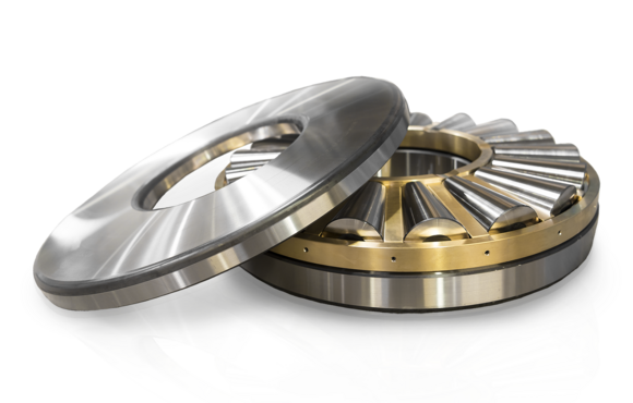
Bearing Design
Single direction tapered roller thrust bearings are dismountable and non-latching bearings which can be used in symmetrical or asymmetrical designs. In the symmetrical tapered roller thrust bearing, shaft and housing washer consist of a tapered raceway and a guiding flange. In the asymmetrical version, one of the bearing washers has a smooth raceway so misalignments between housing and shaft can be compensated. Tapered roller thrust bearings can absorb very high axial forces from a single direction.

Double-sided tapered roller thrust bearing

Roller profiling and tension distribution of tapered rollers in comparison. Left without profiling, right with profiling
Due to the logarithmic profiling of the tapered rollers, damaging edge tension and resulting premature failure are avoided.
Bearing Clearance
The bearing clearance for tapered roller thrust bearings is adjusted only after installation according to operating conditions. The temperature-dependent length variation of the operating components must be considered.

Cage
By default, KRW tapered roller thrust bearings are equipped with a solid brass cage (suffix: M). Other cage designs are available on request or chosen for specific applications and labelled accordingly on the bearing.
Suffixes
Compensation of Angular Misalignments
Tapered roller thrust bearings are not suitable for compensation of misalignments. Misalignments cause edge stresses between rolling elements and raceways and produce additional stresses in the bearing which reduce its operating life.
Speed
The kinematic limiting speed nG is a practical mechanical limit value and is based on the mechanical fatigue strength of the rolling bearing as a function of its installation situation and lubrication. The limit speed must not be exceeded even under optimum operating conditions without prior consultation with KRW.
The DIN ISO 15312 (Rolling bearings - Thermal speed rating) does not specify a thermal speed rating nth for these bearings.
Admissible Operating Temperatures
The admissible operating temperature of a bearing is limited by cage material, dimensional stability of the bearing components (ball race and rolling elements), as well as lubrication. By default, KRW bearings are stabilised up to 200°C (S1). KRW provides roller bearings for higher operating temperatures on request.
Dimensioning
For dynamically loaded bearings
The service life formula according to ISO 281 L10 = (C/P)p for dynamically loaded bearings requires an equivalent load (P) from constant direction and size. To calculate P, calculation factors and the ratio of axial and radial load are required.
Equivalent Dynamic Bearing Load Pa
The equivalent bearing service life for the spherical roller bearings depends on the ratio Fa/Fr . The equivalent dynamic bearing load can be determined using the following formula:

| Pa | equivalent dynamic load | [kN] |
| Fa | dynamic axial force | [kN] |
For statically loaded bearings
Dynamic dimensioning loses its validity for bearings rotating at very low speeds (n x dm ≤ 4000 mm/min). The static load safety factor S0 is calculated as follows:

| S0 | static load safety factor | [-] |
| C0a | static load rating (from bearing chart) | [kN] |
| P0 | equivalent static bearing load | [kN] |
| n | speed | [min-1] |
| dm | mean bearing diameter [dm = (D+d)/2] | [mm] |
Static load capacity

Minimum Axial Load
A minimum load is required for the reliable operation of a rolling bearing. If the minimum load is not reached, slippage may occur. Tapered roller thrust bearings are protected against slippage exclusively through a minimum axial load. The calculation for the minimum axial load for tapered roller thrust bearings is shown in the following formula:


