
Adjacent Structures
Arrangement of the Bearing Position
When designing and constructing the shafts, it is necessary to know the installation space of the rolling bearing. Generally there are two approaches: the bearing you are looking for is adjusted to fit the existing structure or the bearing determines the mating structure. As the dimensions of the rolling bearings are standardized according to the DIN 616 dimensional plan, the outer geometry can be determined through the bearing identification.
When new components are designed, the bearings and the abutment dimensions are adapted to one another. It is a different case with design modifications. Here the outer geometries of the existing parts are usually given and the bearings must be designed accordingly. If standard bearings cannot be used, special solutions must be developed.
Rolling bearings with a radial load are radially supported on the complete circumference in order to prevent a point contact overload.
Axial Location of Roller Bearings
The axial location of the various roller bearings is very much dependent on their type. The following figure shows the difference between a non-locating and a locating bearing arrangement using the example of two deep groove ball bearings.
The left bearing is a locating bearing. It has to support axial forces; thus, it needs to be axially located. The bearing on the right is a non-locating bearing. It does not have to support any axial forces and can move axially through an outer ring that is not axially located. An axial displacement of the bearing is thus possible, as occurs, for example, in the event of thermal expansion.

Support of the bearing on the entire circumference
In the following three graphics, the symbols ■ and □ illustrate the task of the radial locations in the various bearing types and mounting types. The symbol ■ stands for locations which need to support significant axial forces. The symbol □ stands for locations which only have the purpose of preventing axial slipping of the ring.
The next figure shows the axial location for different types of locating bearings. The inner and outer rings are fixed on both sides here.

Axial fixing of locating bearings
The graphic below shows the axial fixing for non-locating bearings. The location depends on the model as well. For example, in the case of a bearing with a loose inner or outer ring both rings need to be axially located.

Axial fixing of non-locating bearings
Special fixing needs to be used for adjusted or floating bearing arrangements which transmit axial forces in only one direction. This is explained in the next figure. The respective rings are fixed axially on one side.

Axial fixing of adjusted or floating bearings
Different fastenings are used for axial fixing:
-
Adjacent structures, e.g. housing lid, gears, spacer rings
-
Shaft/housing locking rings
-
Spring elements (primarily used for axial preload)

Axial fixing: housing lid for locating of outer rings, locking ring for locating of inner ring (F= locating bearing, L= non-locating bearing)
An exception to this is the floating bearing arrangement, as shown in the next figure. Here the two bearings used are not axially located, but instead the bearings are axially fixed.

Floating bearing arrangement
Floating bearings, in which the displacement is realized within the bearings, are to be fixed like locating bearings. The graphic below shows an example with two cylindrical roller bearings of the type NJ.

Floating bearing arrangement with cylindrical roller bearings of type NJ; s= axial clearance
Another option for axial fastening is locating by means of a clamping nut. The clamping nut is additionally secured against torsion with a lock washer as shown in the next figure.

left: adapter sleeve with groove nut and lock washer | right: tapered press fit with groove nut and lock washer
The axial locations listed above are the most commonly used fixings. Location with a lock screw is less common. Here, the spacer ring is pressed against the bearing outer ring with a screw that is integrated into the housing.

Screw fixing outer ring with spacer ring
Furthermore, there are special solutions for the fastening of bearings, which often have a deviation in the bearing design. In these cases the inner and outer rings are equipped with locating units. For this purpose the inner ring is either widened and a fixing hole is drilled or the outer ring is redesigned for direct fixing. The graphic below show examples of such special designs.

Various special solutions for axial fastening
Radial Support of Rolling Bearings
In addition to the axial fixing, the radial support of the bearing in the housing and on the shaft is important. The choice of the mounting condition in the radial direction has a significant impact on the operating clearance and thus on the smooth running and service life of the bearing. Here, the tolerances of the shaft and housing, especially the roundness, are important.
For the radial support of the bearing a tight fit for the inner and/or outer ring is selected, depending on the application. For the fit of the bearing rings, the following criteria msut be checked before the design implementation:
-
The bearing rings must be well supported over their entire circumference. This is in direct correlation to the load-bearing capacity of the bearing.
-
The individual rings must not move or slip on their counterparts in the circumferential direction.
-
Non-locating bearings need to compensate for changes in length of the shaft and of the housing.
-
The bearings can be mounted or removed without any great effort.
The bearing seats need to comply with certain reference values for form and measurement tolerances as well as for surface quality. The reference values for this can be found in the table below.
| Tolerance class of the bearing | Bearing seat position | Machining tolerance | Cylindricity tolerance | Axial runout tolerance | |||
| Load direction rotating t1 | Load direction stationary t1 | t2 | |||||
PN (normal tolerance) | shaft | IT 6 (IT 5) | IT 4 / 2 | (IT 3 / 2) | IT 5 / 2 | IT 4 / 2 | IT 4 (IT 3) |
PN (normal tolerance) | housing | IT 6 (IT 7) | IT 4 / 2 | (IT 5 / 2) | IT 5 / 2 | IT 6 / 2 | IT 4 (IT 5) |
PN (normal tolerance) | housing | IT 7 (IT 6) | IT 5 / 2 | (IT 4 / 2) | IT 6 / 2 | IT 5 / 2 | IT 5 (IT 4) |
P6 | shaft | IT 3 / 2 | (IT 2 / 2) | IT 4 / 2 | IT 3 / 2 | IT 3 (IT 2) | |
P6 | housing | IT 4 / 2 | (IT 3 / 2) | IT 5 / 2 | IT 4 / 2 | IT 4 (IT 3) | |
P5 | shaft | IT 2 / 2 | IT 3 / 2 | IT 2 | |||
P5 | housing | IT 3 / 2 | IT 4 / 2 | IT 3 | |||
P4, SP | shaft | IT 1 / 2 | IT 2 / 2 | IT 1 | |||
P4, SP | housing | IT 2 / 2 | IT 3 / 2 | IT 2 | |||
For the right fit, the load-rotation conditions must first be determined. The different variants are listed in the next figure.

| Rotation conditions | Example | Graphic | Load case | Fitting |
Rotating inner ring | Shaft with gear | (a) | Rotating load on inner ring | Inner ring: tight fit |
Stationary load direction | ||||
Stationary inner ring | Centrifuge, vibrating screen | (b) | Stationary load on inner ring | Inner ring: loose fit |
Rotating load direction | ||||
Stationary inner ring | Car front wheel | (c) | Stationary load on inner ring | Inner ring: loose fit |
Stationary load direction | ||||
Rotating inner ring | Indexing table / positioning | (d) | Rotating load on inner ring | Inner ring: tight fit |
Rotating load direction |
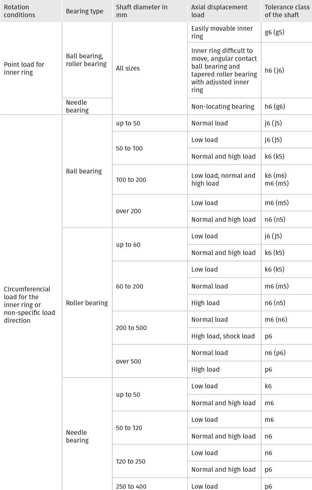
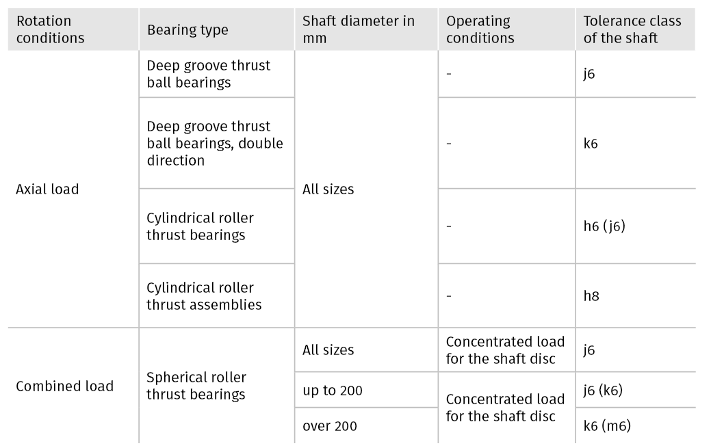
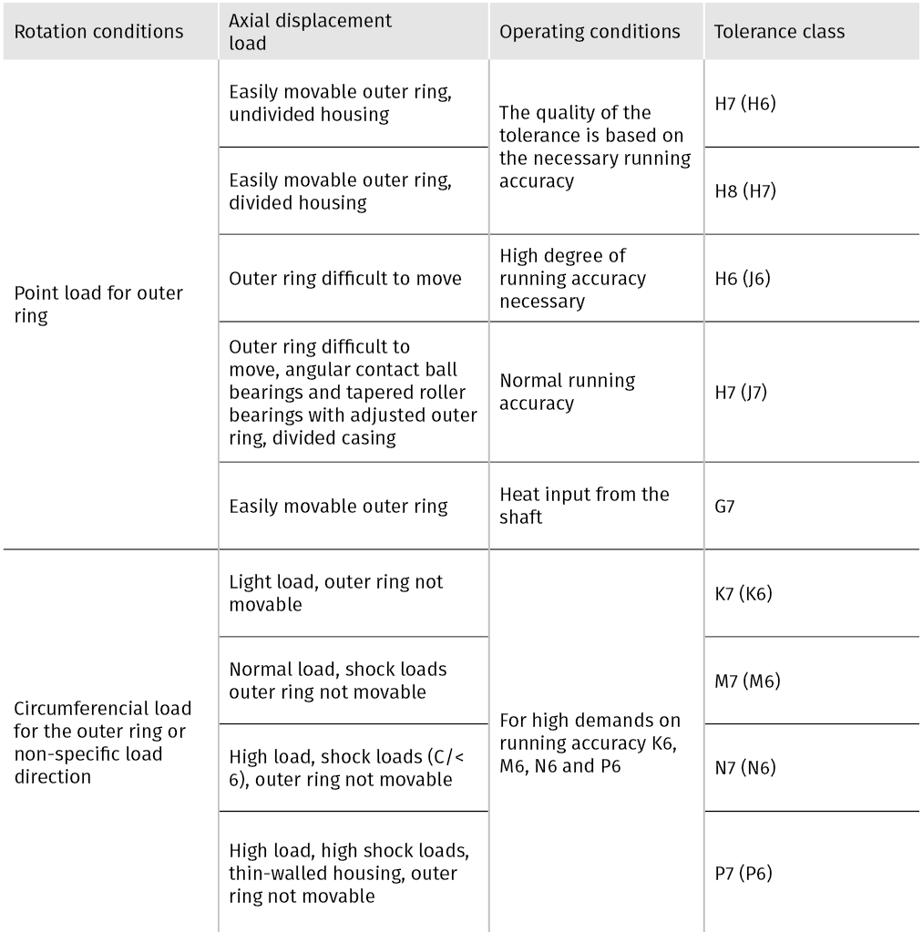
Fit Recommendations for Rolling Bearings
The following tables give recommendations for the selection of the fits of the inner and outer ring depending on the rotational conditions, bearing types, shaft and housing diameters as well as load cases. The tolerance values of the fits for shaft and housing are specified in DIN EN ISO 286.
Fit recommendations for specific load conditions – Radial bearings
Fit recommendations for specific operating conditions – Thrust bearings
Fit recommendations for specific operating conditions – Radial bearings
Fit recommendations for specific operating conditions - Axial bearings

Types and Examples of Fits
The next illustration shows a sample bearing and the corresponding fit for the housing/shaft. Upper case letters stand for the standard bore and lower case letters for the standard shaft. The fitting types - clearance fit, transition fit and interference fit - are marked in color. This shows that a clearance fit creates a gap between the components. In contrast, in the case of an interference fit the components overlap, which leads to a tight fit of the respective ring. It also prevents the ring from rotating due to a tangential force. The interference fit causes an expansion of the inner ring and a constriction of the outer ring. This change in the ring geometry affects the raceway and must be taken into consideration in advance.
")
Overview of fits (illustration greatly exaggerated)
When selecting the fits, different influencing factors need to be considered. In addition to the tight fit explained above, there are also mechanical limits that must be taken into account. These relate to the stress conditions in the inner ring in the case of an expansion, as occurs with a transition or interference fit.
Mounting Condition
The specifications of DIN 5418 can be used as an aid in the design and structural implementation of the adjacent structures. The installation dimensions play an important role here.
First, the manufacturing-related edge conditions are examined. If the bearing is pressed onto its seat, its end face rests against the contact surface of the shaft or the housing. The edge conditions of the two touching surfaces must therefore be adapted to allow full surface fitting of the mating surfaces. The shaft and housing shoulder may be the only point of contact on the bearing. In principle, the edge condition on the shaft and housing seat must be smaller than the smallest edge condition of the bearing ring. As an alternative to a radius, an undercut can be incorporated into the shaft. For this, the contact surface must be ensured. Also, the notch effect should be taken into account in advance.

Radii on the contact surfaces
The contact surface (shoulder) must also be designed in accordance with DIN 5418. The correct dimensioning of the shoulder height is particularly important because it ensures correct load transmission. The limits for the height dimensions are specified in the bearing tables. The respective radii and minimum heights are based on the radius or the chamfer of the corresponding bearing ring and cannot be universally specified.
Tapered roller bearings and angular contact ball bearings occupy a special position. Here, the shoulder heights on the contact surfaces are different.

Shoulder height tapered roller bearing
When mounting thrust bearings, the height of the contact surfaces must also be taken into account (see DIN 5418). If the axial fixation of bearings with circumferential grooves cannot be implemented in the structural design of the mating parts, a snap ring is used to secure it. It is not suitable for transmitting axial forces.

Axial fixing with a snap ring
Additional axial fixings may be designed individually. The basis for this is the mechanical integration of components into the overall assembly. The locating and non-locating bearings are to be taken into consideration here.
When a bearing is pressed onto a shaft, the bearing should only form a tight fit with the shaft at its mounting position. For this reason, shaft shoulders in front of the bearing seat often have a smaller diameter. If a shouldered shaft piece is not possible, a loose fit / clearance fit should be incorporated in front of the seat. There is also a chamfer on the respective shaft ends, which makes assembly easier. All edges should be broken and free of burrs.
Housing Design
If the outer ring is not well supported in the housing bore, the outer ring of the bearing deforms into an oval shape under the pressure of the radial load.

Oval deformation of the outer ring due to load
If the permissible deformation of the housing has been reached due to the forces acting, it must be reinforced. This stabilizes the outer ring and ensures the roundness of the bearing to a certain extent.
The following assumptions are made for the minimum wall thickness:
hA=(1.5 to 2.0) ∗ (D − d) /2
hB=(0.7 to 1.2) ∗ (D − d) /2
hC=(0.15 to 0.25) ∗ (D − d) /2
The lower right figure shows the wall thickness variable. Here, it is imperative that the strongest wall is located in the direction of the force, because the force and the opposite support point deform the material in between the most. The lateral and upper wall areas form a resistance against general deformation of the outer ring.
The left figure shows a variance of different wall areas and the corresponding changes in the balance of forces. The objective is to achieve an acceptable ratio between the dynamic load P and the radial force FR.
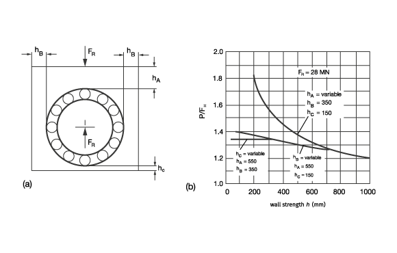
Left: designation of wall thickness | Right: example of the load on the bearing with different wall thicknesses (P = equivalent load, FR = radial load)
The distribution of support points on the housing is also very important. A rolling bearing connects rotating and non-rotating components in a machine. In most cases, the housing is connected to an adjacent structure. The correct arrangement of the support points must be ensured, as this determines the transfer of forces into the adjacent structure. If a support point is used for the housing, the force can only be transmitted to the surrounding components via this single point. Therefore, multiple support points have a positive effect on the balance of forces.

Housing with two support points
Environmental Influences and their Prevention
The service life of rolling bearings is crucially dependant on environmental factors. Contamination has a particularly strong impact. If it reaches the interior of the bearing, it can cause premature damage. Further information on damage to the bearings due to contamination can be found in ISO 15243.
In order to protect the bearing from contamination, sealing points must be provided in the structural design. These represent a barrier between the interior of the bearing and the environment.

Principle of a sealing point: (1) lubricant, (2) sealing unit, (3) contamination
The lubricant prevents metallic contact between the rolling elements and the bearing ring. For this purpose the lubricant must be pure and contamination-free. Contaminants alter the lubricant and may damage the bearing.
For the design of the sealing points, the installation situation, the sealing concept and the sealing material must be defined in advance. An individual sealing concept is necessary for every application. A distinction is made here between static and dynamic seals.

The sealing concept must meet certain requirements, which must be checked and adhered to:
-
Effective tightness against contamination and fluids
-
Prevention of lubricant leakage
-
Low coefficient of friction (for contacting seals)
-
Temperature resistance
-
Maximum rotational speed in the sealing gap (for contacting seals)
-
Chemical resistance
-
Sufficient service life
-
Efficient use of installation space
The selection of the sealing material is also a decisive criterion when designing the sealing point. The following features are important in this context:
-
Operating temperature
-
Chemical compatibility
-
Mechanical properties
-
Dynamic-mechanical behavior
-
Setting behavior
-
Friction and wear behavior
Different materials can be used for contact seals. Frequently used are elastomers such as:
-
NBR (nitrile butadiene rubber)
-
HNBR (hydrogenated nitrile butadiene rubber)
-
ACM (acrylate elastomer)
-
FKM (flouroelastomer)
-
EPDM (ethylene-propylene elastomer)
Optimum sealing can only be achieved if the seal contacts on a suitable surface. If the surface has imperfections such as scratches, gooves, pores, inadmissible roughness, insufficient hardness or helical surface structures, this can lead to a leakage of the seal.
The sealing surface should have the following features:
Surface quality of sealing points
| Seal running area | Surface roughness | Minimum hardness of the running area |
Sliding surface for radial seals | Ra = 0.2 μm to 0.8 μm Rz = 1.0 μm to 4.0 μm Rz1max ≦ 6.3 μm | 600 HV or 55 HRC |
Sliding surface for rods and piston seals | Ra = 0.05 μm to 0.3 μm Rmr(0) 5% / Rmr(0,25·Rz) 70% Rz1max ≦ 2.5 μm | 600 HV or 55 HRC |
Contact surfaces | Ra ≦ 1.6 μm Rz ≦ 10.0 μm Rz1max ≦ 16.0 μm | - |
The use of hardened, helix-free rings is recommended for contact seals. These can serve as a seal running area and are exchangeable.