
Deep Groove Ball Bearings
single direction, metric
- Universally applicable
- Absorption of radial and axial forces
- Suitable for very high speeds
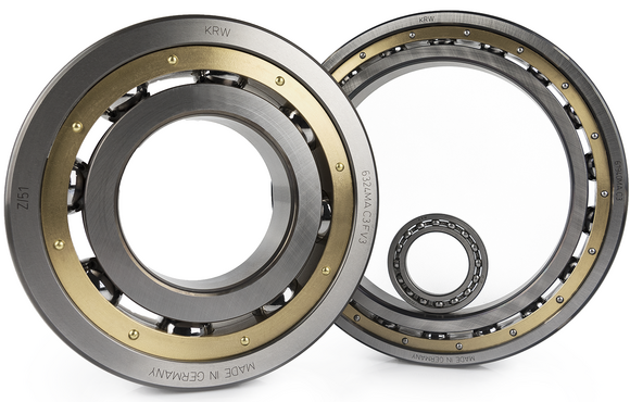
Deep groove ball bearings are the most commonly used type of rolling bearings. In addition to radial forces, they can also absorb axial and combined forces and are particularly suitable for high speeds. Deep groove ball bearings cannot be disassembled and only allow a small tilting angle.
Standards
The general dimensions of single row deep groove ball bearings are standardised in ISO 15 (Radial bearings - Boundary dimensions, general plan), DIN 616 (Rolling bearings - Dimensions), and DIN 625-1 (Radial deep groove ball bearings). The dimensions of the circular groove and circlip correspond to ISO 464 (Radial bearings with snap ring), DIN 616, and DIN 5417 (Securing parts for rolling bearings - Snap rings for bearings with ring groove).
Bearing Design
Deep groove ball bearings are non-latching bearings that cannot be disassembled. In addition to radial forces, they also absorb axial forces from both directions. Depending on bearing clearance, contact angles are adjusted in the process. The radial load limit for ball bearings is significantly lower than for roller bearings with line contact due to the point contact.

Formation of pressure angle under acting axial forces
Bearing Clearance
KRW supplies deep groove ball bearings in normal clearance (CN) in accordance with DIN 620-4 (Radial internal clearance) and ISO 5753-1 (Rolling bearings - Internal clearance), but they are also available in all clearance classes with restricted clearance or special clearance.
| ||||||||

Cage
By default, KRW deep groove ball bearings are equipped with a two-piece brass cage (suffix: M). Other cage designs are available on request or chosen for specific applications and labelled accordingly on the bearing.
Special Suffixes
| DB | Bearing set consisting of two single row deep groove ball bearings in O-arrangement, suffix followed by a character marking the preload level or clearance value. |
| DF | Bearing set consisting of two single row deep groove ball bearings in X-arrangement, suffix followed by a character marking the preload level or clearance value. |
| DT | Bearing set consisting of two single row deep groove ball bearings in tandem arrangement, suffix followed by a character marking the preload level or clearance value. |
Compensation of Angular Misalignments
Deep groove ball bearings are of limited suitability for compensation of misalignments. The admissible misalignment between inner and outer ring depends on the bearing size, the internal bearing design, the clearance fit, and the acting of forces and moments.
Misalignments cause harmful ball movement and produce additional stresses in the bearing which reduce its operating life.
Speed
KRW distinguishes between kinematic limiting speed nG and thermal reference speed nth. The kinematic limiting speed is a practical mechanical limit value and is based on the mechanical fatigue strength of the rolling bearing as a function of its installation situation and lubrication. The limit speed must not be exceeded even under optimum operating conditions without prior consultation with KRW.
The thermal reference speed represents the equilibrium between the heat generated in the bearing by friction and the heat flow dissipated. It is standardised in DIN ISO 15312 (Rolling bearings - Thermal reference speed).
Admissible Operating Temperatures
The admissible operating temperature of a bearing is limited by cage material, dimensional stability of the bearing components (ball race and rolling elements), as well as lubrication. By default, KRW bearings are stabilised up to 200°C (S1). KRW provides roller bearings for higher operating temperatures on request.
Dimensioning
For dynamically loaded bearings
The service life formula according to ISO 281 L10 = (C/P)p for dynamically loaded bearings requires an equivalent load (P) from constant direction and size. To calculate P, calculation factors and the ratio of axial and radial load are required.
Equivalent Dynamic Bearing Load P
For a purely radially loaded deep groove ball bearing acting as a floating bearing, the following applies:

| P | equivalent dynamic load | [kN] |
| Fr | dynamic radial force | [kN] |
The equivalent bearing service life for axially loaded deep groove ball bearings depends on the ratio Fa/Fr (axial force / radial force). The equivalent dynamic bearing load can then be determined using the following formula:

| P | equivalent dynamic load | [kN] |
| Fr | dynamic radial force | [kN] |
| Fa | dynamic axial force | [kN] |
| e | calculation factor, see chart | [kN] |
| X | calculation factor, see chart | [kN] |
| Y | calculation factor, see chart | [kN] |
The calculation factors X and Y depend on the ratio:

| C0 | static load rating, see product chart | [kN] |
| f0 | static calculation factor, see product charts | [-] |
The absorption of axial forces is related to the contact angle of the bearing which is adjusted by the operating bearing clearance. The factors e, X, and Y can be taken form the following table depending on the bearing clearance.
If a calculated value lies between the specified values, the surrounding values must be taken and interpolated to the desired value. The table values only apply to the fits shaft: j5 to k5, housing: J6.
| Bearing clearance CN | Bearing clearance C3 | Bearing clearance C4 | |||||||
| f0 · Fa / C0 | e | X | Y | e | X | Y | e | X | Y |
| 0,31 | 0,22 | 0,56 | 2,0 | 0,31 | 0,46 | 1,75 | 0,40 | 0,44 | 1,42 |
| 0,48 | 0,24 | 0,56 | 1,8 | 0,33 | 0,46 | 1,62 | 0,42 | 0,44 | 1,36 |
| 0,86 | 0,27 | 0,56 | 1,6 | 0,36 | 0,46 | 1,46 | 0,44 | 0,44 | 1,27 |
| 1,60 | 0,31 | 0,56 | 1,4 | 0,41 | 0,46 | 1,30 | 0,48 | 0,44 | 1,16 |
| 3,10 | 0,37 | 0,56 | 1,2 | 0,46 | 0,46 | 1,15 | 0,52 | 0,44 | 1,10 |
| 6,20 | 0,44 | 0,56 | 1,0 | 0,46 | 0,46 | 1,00 | 0,56 | 0,44 | 1,00 |
For statically loaded bearings
Dynamic dimensioning loses its validity for bearings rotating at very low speeds (n x dm ≤ 4000 mm/min). The static load safety factor S0 is calculated as follows:

| S0 | static load safety factor | [-] |
| C0 | basic static load rating (from bearing chart) | [kN] |
| P0 | equivalent static bearing load | [kN] |
| n | bearing speed | [min-1] |
| dm | mean bearing diameter [dm = (D+d)/2] | [mm] |
Static load capactity
The following correlations apply to deep groove ball bearings stressed by static loads:

Axial load capacity
If deep groove ball bearings are stressed by excessive axial loads, there is a risk of the balls damaging the edges of the raceway. The maximum admissible axial force is therefore related to the static load rating C0. The table below shows this for the most common deep groove ball bearing series.
| radial operating bearing clearance according to | Fa, max / C0 | |||||||
| d ≤ 60 mm | d > 60 mm | |||||||
| Series | Series | |||||||
| 160 | 60 | 62 | 63, 64 | 160 | 60 | 62 | 63, 64 | |
| CN | 0,3 | 0,5 | 0,55 | 0,7 | 0,6 | 0,65 | 0,75 | 0,7 |
| C3 | 0,25 | 0,45 | 0,5 | 0,7 | 0,55 | 0,6 | 0,65 | 0,7 |
| C4 | 0,2 | 0,4 | 0,45 | 0,7 | 0,45 | 0,55 | 0,6 | 0,7 |
For deep groove ball bearings subject to high axial loads, the loaded flanges must be supported over the entire flange height. The height of the flanges can be taken from the bearing charts.
Minimum Radial Load
A minimum load is required for the reliable operation of a rolling bearing. If the minimum load is not reached, slippage may occur. The minimum radial load for deep groove ball bearings is roughly assumed to be 1% of the static load rating C0 of the bearing. If the value falls below this value, consult KRW Application Engineering.


